Vapor compression refrigeration, heat pumps
In a refrigeration plant, we try to maintain a cold chamber at a temperature below ambient. The principle is to evaporate a refrigerant at low pressure (and therefore low temperature) in a heat exchanger in contact with the cold chamber.
For this, we need temperature Tevap of the refrigerant to be lower than that of the cold chamber Tef. The fluid is then compressed at a pressure such that its condensation temperature Tcond is greater than the ambient temperature Ta.
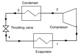
It is then possible to cool the fluid by heat exchange with ambient air until it becomes liquid. The liquid is then expanded at low pressure by isenthalpic throttling, and directed into the evaporator. The cycle is thus closed.
Figure below illustrates the enthalpy transfers that take place in the facility. Small arrows pointing downwards represent the heat exchange, which, as can be seen, do not infringe the second law of thermodynamics, heat flowing from warmer areas to colder areas.
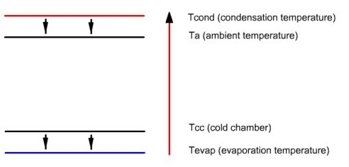
The long upwards arrow represents the enthalpy contribution of the compressor, which can raise the temperature of the fluid (note: the amounts of heat are not proportional to the length of arrows).
The effectiveness of such a cycle is defined as the ratio of useful energy to purchased energy. Thus it is the ratio of heat extracted from evaporator to compressor work. Because its value is generally greater than 1, we prefer to speak of Coefficient of Performance or COP.
In a refrigeration cycle, the practical effect is the extraction of heat by the evaporator. We can also design a machine whose useful effect is heating by waste heat available in the condenser. We call such a machine a heat pump, whose cycle is very similar to that used in refrigeration. It differs only by temperature levels, and therefore the working fluid.
Components
In terms of thermodynamics, a refrigerator is composed of four elements:
The evaporator usually consists of two corrugated flat plates welded against each other, the refrigerant flowing in the channels formed by the corrugations. It generally lines the "freezing" compartment of the refrigerator (the frost layer forms on it). The plate between the flow channels operates as a fin to increase the thermal contact between the refrigerant and the cold compartment. This evaporator is connected to the rest of the machine by two tubes that cross the insulated wall. One of them is connected to the compressor suction, the other to the expansion valve;
The condenser is the black grill located on the refrigerator backside, consisting of coiled tubing supported by metal plates which firstly increase the heat exchange with the air, and secondly reinforce the mechanical rigidity. It is connected to the compressor outlet and expansion valve;
In most cases, the compressor is not directly visible because it is contained in a metal block mounted on rubber cushions to prevent vibrations, out of which exit an electric wire and two input and output fluid pipes. Such a compressor, generally of piston type, is called a hermetic compressor, which has the advantage that the engine is directly cooled and lubricated by the working fluid, without need for oil;
The expansion valve usually consists of a single capillary tube, and sometimes is a thermostatic valve. Before entering the valve, the liquid is slightly subcooled, this ensures that the body is not supplied with vapor, and this increases the performance of the refrigerator.
Journey to the heart of a refrigerator
To improve your understanding of its operation, and understand its thermodynamic databases, a 3D clip (in French) was done by the company Paraschool .
This simple clip is aimed at beginners as well as advanced students. It allows you to view the location of thevarious components in the refrigerator, the route of the thermodynamic fluid , and to obtain values of the thermodynamic state (temperature, pressure, as steam) at various points of the operating conditions for summer or winter.
The clip uses ShockWave, whose installation will automatically be proposed.
Refrigerants
The first refrigeration cycles that were made around 1875 used fluids such as ammonia, sulfur dioxide or carbon dioxide. Subsequently, in the first half of the twentieth century emerged new fluids derived from methane and ethane (chlorofluorocarbons CFCs) and hydrochlorofluorocarbons (HCFCs).
For many reasons, both technical (thermodynamic performance, compatibility with oils, seals, metals, acceptable pressures etc.) and social acceptability (low flammability and toxicity etc.), these fluids have gradually taken the place of the old, in the exception of ammonia, still used in industrial facilities, including food.
In particular, a CFC and an HCFC, R12 (CCl2F2) and R22 (CHClCF2), have come to be used in 75% of the French fleet of refrigeration (1998), while all of these fluids represented over 90% of the total.
Two environmental concerns came abruptly to question the widespread use of CFCs: the breakdown of the ozone layer and the increasing greenhouse effect. As explained section 1.2.2, it was very quickly decided to stop production of CFCs and halons, and to challenge that of HCFCs, as they still contain chlorine. All these measures led to the industrial refrigeration major technological revolution that began in 1994 and is not complete.
Problems occur differently in the case of designing a new installation or changing the fluid in an existing one. In the latter case, it is necessary that the thermodynamic properties of the replacement fluid are similar to those of the original, whereas in the first case the change can sometimes lead to improved performance of the facility. In any case, many technological problems must be studied, such as compatibility with lubricants, choice of the dehydrator, adjusting the expansion valve etc.
To complicate things, regulations differ between countries, depending on commitments they have taken under international agreements. A final element to consider is that large uncertainties remain for the future, especially as regards the fate of high GWP HFCs.
Book references
Chapitre 9
An excerpt of the textbook chapter is freely downloadable with the agreement of CRC Press
Available Diapason sessions
Diapason sessions dealing with refrigeration cycles are given in the table below. Session S30En is specifically dedicated to technology, while others allow you to build in Thermoptim various models of refrigeration cycles:
in session S31En, you study simple cycles;
session S32En allows you to build up the exergy balance of the machine;
session S33En allows you to study the cycle of a heat pump and size of the evaporator.
n° | content | steps | soundtrack duration |
|---|---|---|---|
S30 | Technologie des machines frigorifiques et pompes à chaleur | 25 | 19 mn 30 s |
S31En | 27 | 12 mn 35 s | |
S32En | 9 | 6 mn 40 s | |
S33En | 15 | 9 mn 30s |
Getting started, guidance page for practical work
A getting started guide allows you to learn how to model a vapor compression refrigeration cycledans Thermoptim.
There is no guidance page for practical work on refrigeration cycles, but the one on cooling towers makes use of such cycles.
Exercises and personal activities
Some exercises are provided.
