Displacement compressors
Principle of operation
A displacement compressor is characterized by encapsulation of the flow passing through it in a closed volume which is gradually reduced. A return of this fluid in the direction of decreasing pressure is prevented by the presence of one or more movable walls. In this type of machine, the kinetic energy imparted to the fluid usually does not play any useful role, unlike that which happens in turbomachinery.
By design, the displacement compressors are particularly suitable for processing relatively low fluid flow rates, possibly highly variable, and under relatively high pressure ratios.
Their operating principle is: a fixed mass of gas at suction pressure P1 is trapped in a chamber of variable volume. To increase pressure, the volume is gradually reduced in a manner which differs according to the technique used. Generally, the process follows a law close to a polytropic.
Piston compressors
In a piston compressor the chamber is the volume defined by a cylinder, one of its bases being fixed and the other being a movable piston in the cylinder bore, driven by a connecting rod system.
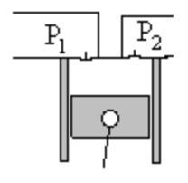
By the end of compression, the chamber is in communication with the discharge circuit so that the compressed gas at pressure P2 can emerge. A new mass of gas at pressure P1 is then sucked into the inlet pipe, and so on, the operation of the machine is cyclical.
The organs that control the discharge or admission are, in piston compressors, valves operated automatically by pressure differences between the chamber and the discharge or admission manifold.
One denotes Vs the volume swept by the piston between its two extreme positions, and "dead space" eVs the minimum volume of the compression chamber. In the current achievements, e is the order of 3 - 5%.
Because of the existence of the dead space, displacement compressors have a particular characteristic: their apparent displacement is less than their geometric displacement. A certain mass of fluid remains trapped in the compressor at the end of discharge , thus reducing the useful volume of the machine. We characterize the displacement reduction by a quantity lambda called volumetric efficiency.
Low volumetric efficiency is not inherently disadvantageous in terms of energy: it simply means that the mass flow passing through the compressor is less than that theoretically corresponding to the displacement. However, it is economically disadvantageous, since for a given specification, it leads to oversizing of the cylinder, and thus to a higher investment.
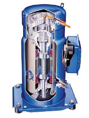
Here is a clip showing the operation of a hermetic piston compressor manufactured by company Maneurop.
Screw compressors
In screw compressors, compression is achieved by varying the volume between two rotors of appropriate shape, enclosed in a particular cylinder
The two rotors, or mobiles, have mating profiles, one forming lobes (male rotor), and the other cells (female rotor). These profiles are developed along the axis with a fixed pitch screw. The cylinder has a section formed by two intersecting circles. It surrounds the rotors with a very small clearance to minimize leakage. Ports are arranged at the inlet and outlet to allow transfer of fluid. There is no valve here.
The number of lobes and alveoli not being the same, both screws rotate at different speeds, which has the effect of moving axially their line of contact by pushing the enclosed fluid. After aspiration, the cell volume of trapped gas is gradually reduced until the rotation of the rotor discovers the exhaust hole. The discharge then continues to complete drain.

In this type of compressor rotors are synchronized either by gears or by mutual mechanical drive. In the latter case, it is imperative to carefully lubricate the contact line between the male and female lobes, which is done by injecting a liquid that can be oil or water, or, for refrigeration applications, the refrigerant in the liquid state.
This injection, performed in relatively large quantities (about ten liters of oil per m3 of gas sucked), is also used to seal and cool the compression to approach an isothermal operation, better in energy terms. However, it is then necessary to separate the liquid from the compressed gas, which requires special equipment and leads to additional pressure drop.
In screw compressors, as also in the vane or lobe compressors, the compression ratio is determined by the geometry of the machine, which determines the internal volume ratio Vi = V1/V2c, construction volumetric ratio that can only be modified by acting on the shape of the exhaust opening (the index c refers to the structural characteristics).
It follows that their compression ratio is fixed and the machine does not automatically adjust to different compression ratios, as do reciprocating compressors with valves. However, the absence of valves is an advantage in terms of maintenance, the latter being mechanically highly stressed parts.
If the discharge pressure Pr is less than the constructive pressure P2c, rapid expansion from P2c to Pr occurs at the opening of the exhaust port. Otherwise, there is sudden compression of the gas cell from Pr to P2c, then discharge at this pressure. In both cases, this induces a loss.
Spiral or scroll compressors
The spiral or scroll compressors have operating characteristics close to screw machinery (existence of a constructive Vi and therefore losses by subcompression or supercompression if the compression ratio deviates from the real constructive value).
In this type of compressor, two cylindrical spirals, one fixed and one mobile identically shaped roll without slipping on one another, locking gas pockets of variable volume, providing compression. The gas is sucked at the circumference and discharged at the center.
The advantages of this device are the lack of valves, the simplicity of the mechanism and hence its low cost and its silence, low mechanical losses, the possibility to rotate at high speeds, lack of vibration, light weight, reliability and low torque.
Technological problems are mainly in the machining of spirals and the seal between each spiral and the bottom of its conjugate. These compressors can operate without oil.
Here is a clip showing the operation of a scroll compressor manufactured by company Maneurop.
Modeling assumptions
Machines doing the compression or expansion of a fluid have a very compact design for reasons of weight, size and cost. For similar reasons, they rotate very fast (several thousand revolutions per minute). Each parcel of fluid remains there very shortly.
Moreover, the heat exchange coefficients of gases have low values. Short residence time, small areas of fluid-wall contact, and low exchange coefficients imply that the heat exchange is minimal and that the operation of these machines is nearly adiabatic.
The reference process for compression or expansion with work is the perfect or reversible adiabatic, i.e. the isentropic.
However, in a real machine, irreversibilities take place, mainly due to viscous friction and shock. They have the effect of increasing the fluid temperature and entropy. In an entropy chart, the evolution deviates from the theoretical isentropic vertical (see figure below).
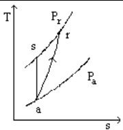
Real adiabatic compression
Calculation method
To calculate the work put into play in a real adiabatic compression, there are two ways to operate:
The first is to introduce an efficiency eta s called isentropic or adiabatic efficiency, which is determined experimentally, as the ratio of isentropic work to real work;
The second way is to introduce the concept of polytropic. For this, we assume that the irreversibilities are uniformly distributed over the entire process. We can then derive a differential equation, assuming that the isentropic efficiency keeps a constant value during any infinitesimal compression. By definition the polytropic efficiency is equal to this infinitesimal isentropic efficiency. This differential equation leads to a simple equation for a perfect gas:
The sequence of steps for calculating a compression with the first approach can be stated as follows:
1) we must first calculate the entropy at suction s(Pa, Ta);
2) we must then reverse in Ts the entropy equation s(Pr, Ts) = s(Pa, Ta);
3) we must calculate the work corresponding to the isentropic process Dhs = h(Pr, Ts) - h(Pa, Ta);
4) we deduce the outlet enthalpy hr = h(Pa, Ta) + Dhs/eta , eta being the isentropic efficiency;
5) Finally, we obtain the discharge temperature Tr by reversing the equation h(Pr, Tr) = hr
The icon of a compressor in Thermoptim is:
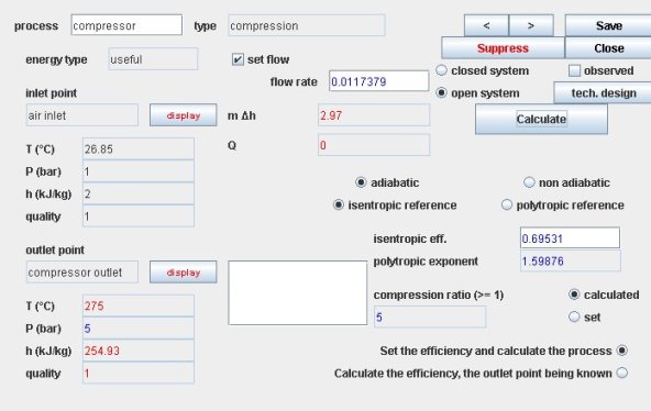
Thermoptim compression screen
The compressor screen offers several thermodynamic settings:
if the compression is adiabatic, we can choose an isentropic or polytropic reference. We must then enter the value of the isentropic or polytropic efficiency
if the compression is not adiabatic, the calculation is then imperatively polytropic. You must enter the values of the polytropic efficiency and exponent
Book references
Thermodynamcs ofcompression
An excerpt of the textbook chapter is freely downloadable with the agreement of CRC Press
Available Diapason sessions
n° | content | steps | soundtrack duration |
|---|---|---|---|
S11En | 16 | 5 mn 45 s | |
S12 | Technologie des compresseurs volumétriques | 24 | 16 mn |
