Heat exchangers
Technology
Heat exchangers are devices for transferring heat between two fluids at different temperatures. In most cases, the two fluids are not in contact, and the transfer is through an exchange area. Within the dividing wall, the heat transfer mechanism is conduction, and on each of both surfaces in contact with fluids, convection almost always predominates.
In many cases, fluids are single phase, whether gas or liquid. However, there are three main types of heat exchangers in which phase changes occur: the vaporizer or evaporator where it vaporizes a liquid, the condenser where steam is liquefied and the evaporative condenser where both fluids change phase.
Although there is a very large variety of models of heat exchangers, the four main categories used in energy systems are:
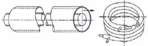
Tubular exchangers
shell and tube exchangers
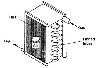
air coils
plate heat exchangers
The exchanger pinch is the minimum difference of temperature within it.
The importance of the pinch is most evident in the problems of design of complex heat exchanger networks, so that powerful optimization methods based on this concept have been developed.
That of Thermoptim, derived from the pinch method, is presented in the section Methodological guides.
Tubular exchangers
Air coils
Modeling assumptions
Three assumptions are generally used to model a heat exchanger:
in first approximation, it can be considered as isobaric;
it is globally adiabatic, that is to say that there is no heat exchange with the surroundings;
heat transfer coefficients and thermophysical properties of fluids keep a constant value at any time in the entire heat exchanger.
In a heat exchanger, the fluid flows can be performed in multiple arrangements.
One can easily show that thermodynamically, the most efficient heat exchanger is the counter-flow heat exchanger, but other concerns than the thermodynamic effectiveness are taken into account when designing a heat exchanger: the maximum permissible temperatures in one fluid, or more often considerations of size, weight or cost.
It follows that the configurations of exchangers that are encountered in practice are relatively numerous.
However, we can gather these configurations in three main geometries:
counter-flow, in which fluids flow in parallel and in opposite directions;
parallel-flow, in which fluids flow in parallel and in the same direction;
cross-flow, in which fluids flow in perpendicular directions.
In general, the design of heat exchangers is a compromise between conflicting objectives, whose two main ones are:
a large exchange area is desirable to increase the effectiveness of heat exchangers, but it results in high costs;
small fluid flow sections increase the values of the heat exchange coefficients and thus reduce the area, but they also increase pressure drops.
Calculation method
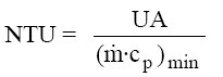
The calculation method we advocate is that of the NTU, or Number of Transfer Units. We content ourselves here with a very concise presentation, excerpts from the first edition of the book Energy Systems available in the links below are much more detailed.
By definition, NTU is defined as the ratio of the product UA of the heat exchanger to the minimum heat capacity rate:
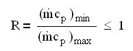
We call R the ratio (less than 1) of the heat capacity rates:
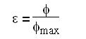
and e the effectiveness of the exchanger, defined as the ratio between the heat flux actually transferred and the maximum possible flux:
We can show that phimax, that would be obtained for a counter-flow heat exchanger of infinite length, is:
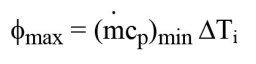
DTi is the difference between inlet temperatures of both fluids
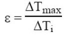
Dtmax beingthe maximum temperature difference within each of the two fluids and not between them, we have:
With these definitions, it is possible to show that there is a general relation of type:
e = f(NTU, R, flow pattern)
For example, a counter-flow heat exchanger, the analytical expressions are for R different from 1:
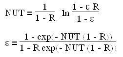
If R = 1 :
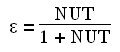
These equations correspond to the chart below:
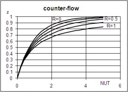
In practice, it suffices to have a set of relationships corresponding to flow patterns representative of exchangers studied, and the design of a heat exchanger is made on the basis on the one hand of the balance equations and on the other hand of the internal equation e = f(NTU, R, flow pattern)
If we know the flow-rates of both fluids, their inlet temperatures and the heat flux transferred, the design procedure is as follows:
we start by determining the outlet temperatures of fluids from the balance equation;
we deduce the fluid heat capacity rates m cp and their ratio R;
the effectiveness e is calculated from DeltaTmax et DeltaTi ;
the value of NTU is determined from the appropriate (NTU, e) relationship;
UA is calculated from equation defining NTU.
In off-design mode, if you know UA, the equation defining NTU gives its value, and you can determine e from the appropriate (NTU, e) relationship.
The balance equation allows you to calculate heat transferred.
In both cases, the enthalpy balance provides the outlet temperatures.
In practice, we do not know UA but A. However, we can often consider that U varies only in the second order, and seek an approximate solution by considering U constant, then recalculate its value for new operating conditions, and iterate until a reasonable accuracy is obtained. It is particularly necessary to operate this way when the exchanger is multi-zone, because only the total area is known, not its distribution among different areas.
Representation in Thermoptim
Recall that an "exchange" process is used to calculate the heating or cooling of a fluid between two states represented by upstream and downstream points .
In Thermoptim it is represented by icon:
As noted above, the "exchange" process can be considered isobaric as a first approximation. The pressure drops are in fact generally relatively low.
In Thermoptim, a heat exchanger is not represented by a particular component, but by a connection established between two "exchange" processes representing the hot and the cold streams.
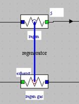
To represent the heat exchanger in the diagram editor, we thus use non-oriented links connecting two components of type "exchange".
A heat exchanger is created in the simulator when an exchanger link exists in the diagram and the two "exchange" components that it connects correspond to two "exchange" processes in the simulator which are sufficiently well defined (it is particularly necessary that their inlet and outlet temperatures are different, that they have been calculated so that the value of Delta H is not zero, and that one is warming while the other cools). By default, the exchanger is initialized with a "counter-flow" type.
Given the assumptions made, the heat exchanger is necessarily balanced in terms of enthalpy, that is to say that the enthalpy transferred by the hot fluid is exactly equal to that received by the cold fluid.
Given that there are four temperatures (two for each fluid) and two flow rates, the problem has five degrees of freedom once the enthalpy is conserved. One can furthermore show that at least one of the two flow rates has to be set, otherwise the problem is indeterminable.
For temperatures, one can either set explicit constraints (for example the fluid inlet temperatures), or implicit constraints (the value of the heat exchanger effectiveness, or the pinch minimal value).
For the problem to have a solution, it is necessary to set a total of five constraints, among which there is a flow rate. If one of them is implicit (effectiveness or minimal pinch), four have to be explicit (3 temperatures and 1 flow rate, or 2 temperatures and 2 flow rates), or otherwise all five have to be explicit (a single flow rate or a single temperature is free). These conditions are necessary, but not sufficient.
Thermoptim proposes several design options matching these degrees of freedom. It is important to be aware they may not have physical meaning and one must always reflect on how the exchanger fits in the system to validate them.
For example, if the flow of one of the fluids is determined by other components or by an external driver, it is absurd to set the exchanger by setting this flow to be calculated. This is especially true when studying a steam generator consisting of three heat exchangers in series: of course the flows of each of the fluids passing through them are generally the same in all three elements, and outlet temperatures of an element are equal to the inlet ones of the next. Thermoptim does not diagnose an aberrant configuration as long as it does not lead to an error, but the calculations will be meaningless.

The figure above shows the screen of a heat exchanger in Thermoptim.
It contains information about the hot fluid in the middle left part, while that for the cold fluid is in the right part.
Besides the values of temperatures, flow rates, heat capacities and enthalpies involved, constraints exist on the temperatures and flow rates used to manage the heat exchanger calculations, allowing one to distinguish between the variables of the problem, those set and those to be calculated.
Possible types of exchangers are: counter-flow, parallel, cross-flow, mixed or not, and multi-pass shell and tube (p-n).
In the bottom left, there are three buttons to optionally specify the absence or presence of implicit constraints on temperatures (see below). In the lower right are placed options for defining the calculation method ("design" or "off-design").
Calculation of the overall heat transfer coefficient U
The NTU method presented above, which is used in the Thermoptim phenomenological version, only provides the product UA of the global heat exchange coefficient by the surface of the exchanger, without the two terms being evaluated separately.
To size the heat exchanger, that is to say calculate its surface, one must first choose a geometric configuration, and also calculate the global exchange coefficient U, which depends on the configuration and thermophysical properties of fluids.
The overall heat transfer coefficient U depends on the distribution of thermal resistances in the exchanger. If the exchange surfaces are equal for the two fluids, it is given by the following equation, where e / lambda represents the resistance of the wall, lambda being here the conductivity of the material component:

The values of convection coefficients hc and hf are based on the thermophysical properties of fluids and configurations of exchange, convective regimes being highly dependent on the flow velocity.
They can be obtained from correlations giving the value of Nusselt number, lambda being here the conductivity of the fluid:
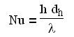
The Nusselt number is a function of Reynolds and Prandtl numbers:
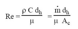
Re depends on the density, flow velocity, the hydraulic diameter and the kinematic viscosity.

Pr depends on the kinematic viscosity, the heat capacity and conductivity of the fluid.
C1, a, b and c are constants, the Nusselt number is almost always given by a relation of type:
The correction of viscosity is made on the basis of the wall temperature. The coefficients C1, a and b vary according to configurations encountered, and the additional term to account for variations in viscosity is often neglected.
In general, the exponent of the Reynolds number is between 0.5 and 0.8, and that of the Prandtl number between 0.33 and 0.4.
The flow regime has a significant influence on the value of Nu.
In cases where Re is less than 2000, the regime is laminar, and if Re is greater than 5000, it is turbulent, with a transition zone, these bounds being not perfectly stable.
For a stabilized laminar flow, Nu = const, the value being between about 4 and 8, depending on the shape of the tube and the mode of heat exchange (constant temperature or flux).
Book reference
An excerpt of the textbook chapter is freely downloadable with the agreement of CRC Press
Available Diapason sessions
n° | content | steps | soundtrack duration |
|---|---|---|---|
S10En | 5 | 1 mn 35 s | |
S11En | 16 | 5 mn 45 s | |
S15En | 16 | 9 mn 50 s |
