Combustion chambers
A combustion chamber must satisfy severe constraints:
ensure complete combustion of fuel;
minimize the pressure drop (which represents an increase in compression)
ensure good temperature stability at the turbine inlet;
and occupy a volume as small as possible while allowing proper cooling of the walls.
The chart below is a section of a flame tube type combustion chamber, very commonly encountered in practice
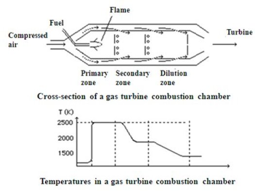
The compressed air exiting the compressor enters on the left side. It splits into two streams, one that provides wall cooling, the other entering directly into the combustion chamber, where it serves as oxidizer for the fuel injected into the central part. Given the low excess air locally, the flame reaches a high temperature (up to 2500 K) in the primary zone. Through holes at the periphery of the flame tube, the outside air mixes with exhaust gases in the transitional zone, where the temperature drops to around 2000 K, and in the dilution zone, where one seeks to achieve a gas flow temperature as stable as possible to avoid the risk of local or momentary overheating.
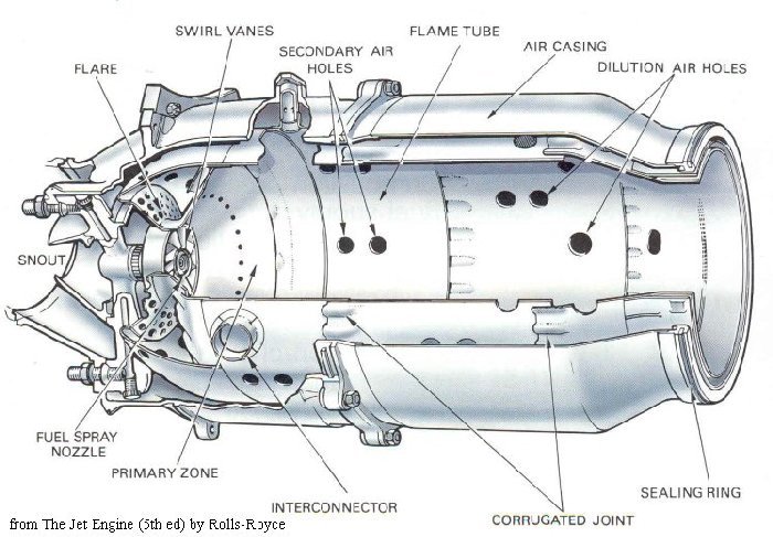
In flame tube cylinder chambers, six to twelve tubes of this type are mounted in parallel around the axis of the gas turbine. They are interconnected in order to balance the pressures and enable propagation of the ignition.
Two other types of chambers are available:
silo chambers: in this case, chambers, separated from the axis, are much larger, allowing better control of combustion, including emission of pollutants (NOx);
annular chambers: the chamber has a single volume, annular, fuel being injected in several points. This arrangement yields a shorter flame and better combustion efficiency.
The efforts of manufacturers now focus on reducing emissions of pollutants, particularly nitrogen oxides.
Thermodynamic characteristics
As a first approximation, the combustion chambers of gas turbines can be considered as isobaric . The pressure drops are in fact generally relatively low. In contrast, the combustion taking place in internal combustion reciprocating engines are not isobaric. The setting of the combustion chamber depends thus very much on the technology that we seek to model.
When the combustion is not stoichiometric, it can be characterized in several ways:
either by excess air e, which as its name implies, represents the amount of air in excess
or by the air factor lambda, which is the term multiplying the air in the combustion equation
or by the richness R, ratio of the number of moles (or mass) of fuel in a quantity of mixture, to the number of moles (or mass) of fuel in the stoichiometric mixture.
For stoichiometric mixture lambda = 1, with excess air lambda > 1, with an excess of fuel (lack of air) lambda <1
These three variables are linked by simple relationships: lambda = 1 + e, and R = 1/lambda
In Thermoptim a combustion chamber is represented by the icon:
The setting of combustion screens is done using lambda.
the first is to give the value of lambda and calculate the end of combustion temperature and the flow-rate of fuel required
the second is to give the value of the end of combustion temperature and to calculate lambda and the flow-rate of fuel required
the third is to give the value of the fuel flow-rate and to calculate lambda and the end of combustion temperature
Book reference
An excerpt of the textbook chapter is freely downloadable with the agreement of CRC Press
Available Diapason sessions
n° | content | steps | soundtrack duration |
|---|---|---|---|
S15En | 16 | 9 mn 50 s | |
S16 | Technologie des chambres de combustion et des chaudières | 9 | 4 mn |
Thermoptim-Light page Calculation of combustions
A page allowing you to make combustion calculations is available.
