Organic Rankine Cycles (ORC )
Introduction
Organic Rankine cycles (ORC) are variants of water steam cycles, which are used when the hot source is low or medium temperature.
Under these conditions, the performance of the steam cycle tends to deteriorate, and it is preferable to use other thermodynamic fluids.
As many of these fluids are organic in nature, it is customary to call them organic cycles, but other types of fluids, such as ammonia or carbon dioxide may be used.
Such a cycle uses a condensable fluid, which is cooled at a temperature and pressure sufficient for it to be fully liquefied before compression. Under these conditions, the compression work is almost negligible compared to the expansion work (although it represents about 60% in a gas turbine). The compressed liquid is vaporized and possibly superheated in the boiler by heat exchange with the hot source, then expanded and condensed. Fluid two-phase state during condensation and vaporization phases is very favorable for heat transfer.
If there is no superheating, it is called a Rankine cycle, and if there is one, a Hirn cycle.
The block diagram of a steam power plant operating on the ideal Hirn cycle is given in figure below. Such a plant includes four basic components:
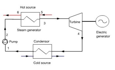
In large plants, the expander is generally a turbine. In smaller ones,screw machines are used, and, for the smallest ones, scrolls.
For detailed information on the operation of this type of cycle and its variants, refer to the portal page on steam cycles.
Cycle architecture
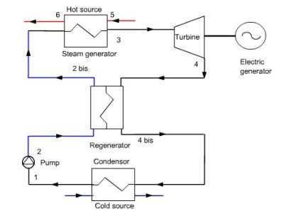
The simplest cycle is the one that has been presented above, but, as for the steam cycle, more complex architectures can be used , based on the same principles: regeneration and reheat. The figure below shows a cycle with regeneration.
In this cycle, the vapor leaves the turbine in 4, in the superheated state. The energy corresponding to the superheating (4 - 4a) is recovered to preheat the pressurized liquid condensate before entering the steam generator ( 2-2 bis).
In addition, ORC cycles may be associated with other cycles to form combined or mixed cycles. The portal page on geothermal plants gives several examples.
Note also that the ORC cycles can be supercritical. CO2 cycles presented in another thematic page is one example.
Finally, the Kalina cycle can be considered as an ORC cycle.
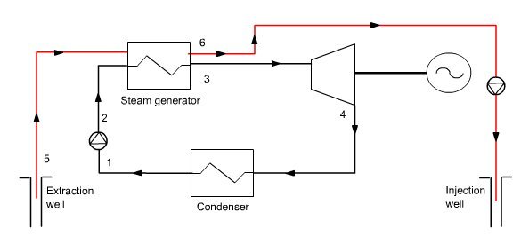
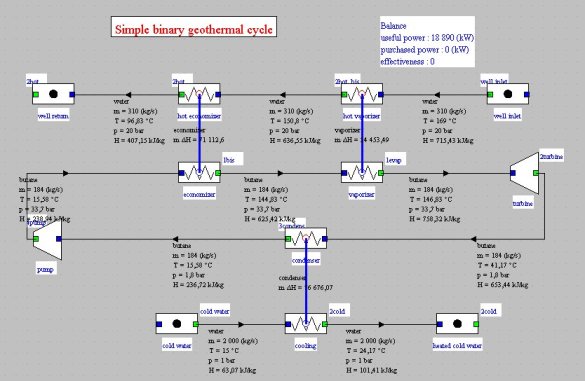
For example, the figures below show the block diagram and synoptic view of a geothermal ORC cycle, said binary, modeled in Thermoptim. It was assumed that the geothermal stream is 310 kg/s hot water in the liquid state at a temperature of 169 °C and pressure of 20 bar.
This water is used to vaporize butane with a slight superheating (2 °C) which is then expanded in a turbine and condensed in a conventional Hirn cycle. The mechanical power output is 18.9 MW.
Applications of ORC cycles
The ORC cycles are facing growing interest in the world since the late 1980s, with three major classes of applications, which represent the main achievements in terms of installed capacity and number of installations:
geothermal plants;
biomass combustion plants;
heat recovery from effluents.
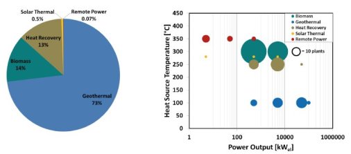
The figures below, from the presentation Application of Organic Rankine Cycles (ORC), by A. Rettig et al., The World Engineer's Convention Geneva in September 2011, provide some quantitative elements. The left figure shows the distribution of installed capacity in the world, and the right one the number of facilities sorted by level of temperature (y-axis) and power magnitude (x-axis) .
A growing number of industrial companies manufacture and install ORC plants, especially in Anglo- Saxon countries.
Fluids for ORC cycles
As shown in the previous right figure, the ORC cycles are used with hot sources of very different temperatures from 100 to 350 °C approximately. Above 350 °C, the steam cycles are generally more efficient, and below 100 °C, except in exceptional cases such as OTEC cycles or solar ponds, the cycle efficiency is so low that the conversion into mechanical energy of the thermal power of the heat source is not justified economically .
This wide temperature range has a direct impact on the selection of thermodynamic fluids, but it is not the sole criterion, far from it. For further analysis of the issue, refer to the portal page that deals with this subject.
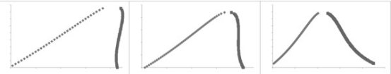
For ORC cycles, it is customary to distinguish three types of fluids: dry fluids, wet fluids and isentropic fluids. This distinction is by the value of the slope δ of the expansion in the entropy chart, defined by δ = dS / dT on the vapor saturation curve:
if δ > 0, the fluid is called " dry";
If δ = 0, the fluid is called " isotropic ";
if δ <0, the fluid is called " wet".
Specifically, the vapor saturation curve of "dry" fluids has a positive slope, that of " isentropic " fluids is infinite and the "wet" fluids have a negative slope. This results in the three forms of saturation curves shown in the figure below (dry left isentropic fluid in the middle, and wet right).
For ORC cycles, " isentropic " or "dry" fluid is generally preferred. However, note that "dry" fluid is not necessarily the perfect one because it can be highly superheated after expansion. We must then consider using a regenerator to recover the heat provided by desuperheating the fluid to saturation, but it can present technological difficulties or induce higher costs.
The recent literature contains numerous publications on the choice of the optimal fluid for a given ORC cycle, but we recommend some caution in the confidence in the announced results, because very often the thermodynamic models used are imprecise and the cycle architectures simplified.
For a discussion on this topic, refer to the portal pages that present models of fluid corresponding to the cubic and associating fluids equations of state.
ORC cycle optimization
The ORC cycle optimization can be a very complex problem. This is particularly the case for some geothermal or waste heat recovery facilities.
The problem is as follows: the heat source is in the form of a flow of geothermal fluid or effluent, at a given temperature, and the system optimization generally seeks to cool as much as possible the heat source, while maximizing the mechanical power generated by the ORC cycle.
As it is a coupled problem, maximizing the performance of the ORC cycle alone often leads not to completely cooling the heat source due to the existence of a pinch at the output of the generator economizer.
This issue is exposed in the portal page that analyze the impact of the pinch on the performance of a steam generator. The method to address this problem is presented in the page on thermal integration.
