Reciprocating internal combustion engines
Introduction
Piston machines occupy a prominent place among internal combustion engines. This situation stems from two causes:
1. By their periodical operation, these machines are particularly suitable for processes where the temperature reaches high values. Being in contact with the fluid at various stages of process, the walls of the machine are subject to an average temperature well below the maximum temperature, whereas in a continuous flow machine such as gas turbine, some parts are constantly subjected to this temperature.
2. Internal combustion engines are widely used for propulsion of vehicles of small and medium capacity. Indeed the piston engine adapts much better to this use than the turbine engine, which is feasible only with very high characteristic speed, and therefore must rotate at considerable speed when power is moderate, with interposition of fragile and expensive reducing gear.
Reciprocating engine capacity ranges for usual application from less than 1 kW to about 1 MW. The crowning achievement use of these machines is the propulsion of road vehicles.
There are two main types of reciprocating internal combustion engines:
1. spark ignition engines, whose principle was established by the French Beau de Rochas in 1860, and the first project carried out by the German Otto in 1876.
2. compression ignition engines, called Diesel, by the name of their German inventor who patented them in 1892.
What distinguishes the two types of engines is not so much the theoretical cycle than combustion characteristics, including kinetics which follow very different laws depending on whether the fuel is volatile or not.In a gasoline engine, fuel is premixed with the oxidizer and we talk of premixed flame, while a diesel engine combustion takes place in a heterogeneous environment where the fuel droplets ignite on contact with hot air: is called diffusion flame.
General mode of operation
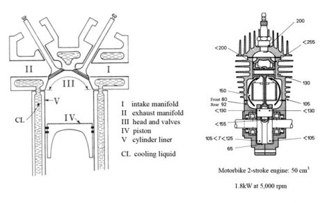
All reciprocating internal combustion engines operate on the same general process described schematically Figure below. A variable volume is defined by a cylinder, one of the bases of which is fixed, called head, and the other is a movable piston in the cylinder bore, driven by a connecting rod system. In a four-stroke engine, the organs that control the inlet or exhaust valves are actuated by push buttons coupled to the drive shaft by a camshaft.
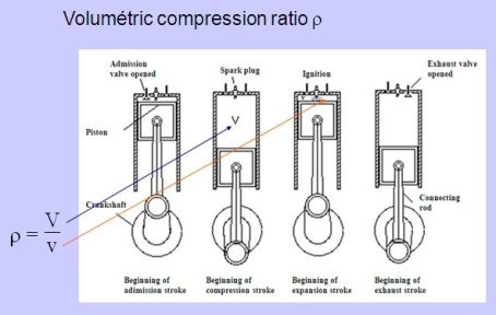
In various ways, depending on whether the engine is two or four stroke (see below), fresh gas is introduced into the cylinder at atmospheric pressure during the intake phase (fuel mixture formed in advance in conventional gasoline engines, clean air in diesel engines).
The piston being at a distance from the bottom of the cylinder, the intake port is closed, the volume V between the piston and the bottom being occupied by a certain charge of fresh gas.
Approaching the bottom of the cylinder, the piston compresses the charge in the volume v of the combustion chamber, that is to say the remaining space when the piston reaches the end of his stroke, called top dead center or TDC. This compression is substantially adiabatic and occurs without appreciable internal friction. The key factor is the operating volumetric compression ratio ro = V/v, a geometric characteristic of the cylinder.
The combustion reaction is then triggered, either by local ignition of the mixture in gasoline engines or by injecting fuel into the compressed air in diesel engines. The combustion occurs during a relatively short time, while the piston continues its stroke. In practice, it occurs in a mode intermediate between the constant volume combustion and combustion at constant pressure. The piston continuing to move away from the bottom of the cylinder, the burned gases expand until the end of the stroke (bottom dead center or BDC), then are evacuated and replaced by a new charge of fresh gas.
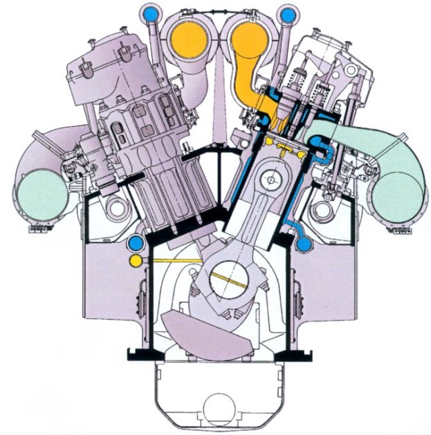
High capacity diesel engine
Figure below shows the general configuration of a Pielstick PC2-6B high capacity diesel engine (up to 18 cylinders of 630 kW, 400 mm bore, 500 mm stroke). An 18 cylinder engine running at 530 rpm developing 11.34 MW has a mass of 130 t. It measures 10.24 m long, 3.6 m wide and 3.8 m in height.
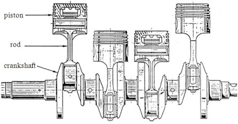
Connecting rod
The figure below shows an exploded view of the assembly formed by a crankshaft, with pistons and connecting rods.
Combustion modes
An important difference between a gasoline engine and a diesel engine is not in the mode of introducing fuel, which in some gasoline engines is also injected, but when the fuel is introduced, which determines the nature of gas when the reaction starts.
In the gasoline engine, fuel is introduced well in advance so that the cylinder is full, when ignition occurs, of a substantially homogeneous mixture. In the diesel engine, fuel is injected at the last moment and burned as and when it is introduced.
For this reason, in general, gasoline engines burn gas or volatile liquid fuels, and diesel non volatile liquid fuels, but one may also burn in gasoline engines liquid fuels with low volatility sprayed very finely, and in diesel pressurized gaseous fuel or volatile liquid fuels.
Four-stroke and two-stroke cycles
According to the method used to evacuate gases and replace them with a fresh charge, there are two operation modes known as four-stroke and two-stroke.
In four-stroke cycles, the most common, the head of the cylinder is pierced by two holes, controlled by valves, which put it in communication with the intake and exhaust manifolds. Note the difference with reciprocating compressors, where valves are not controlled, but opened by differences in pressure between the cylinder and these manifolds.
The evolution of gas pressure and specific volume in the cylinder is often represented in the Watt diagram (Figure below). At the end of expansion in 3, the exhaust valve opens, pressure drops to atmospheric pressure and the piston performs a full stroke to the head thus driving gases out. When it reaches the TDC in 5, the exhaust valve closes and the inlet opens. Moving away, the piston draws a fresh charge of gas. In 4, the BDC, the intake valve closes and compression 4-1 begins followed by combustion 1-2 and expansion. It is therefore a simple cycle in four strokes, hence the name four-stroke engine.

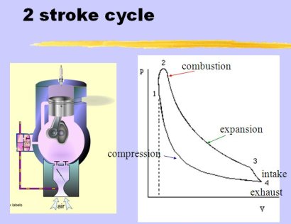
In two-stroke engines, exhaust occurs at the end of the expansion stroke through holes made in the side wall at such a level that they are unmasked by the piston at BDC. At the same time or shortly after, intake ports are opened which connect the cylinder with a manifold filled with fresh gas at a pressure slightly higher than that prevailing in the exhaust manifold.
The opening of the exhaust ports in 3 drops the pressure at the exhaust manifold (Figure 3.1.9), then the opening of the exhaust port produces a sudden burst of fresh gas, which drives flue gases to the exhaust manifold. The discharge gases and their replacement with fresh gas (scavenging) are carried out during a short time at the end of the expansion stroke and the beginning of the next one. The exhaust ports are closed, and then come compression 4-1, combustion 1-2 and expansion. The entire operation takes place in two simple strokes, hence the name two-stroke cycle.
The Diapason session S35En_4t2t prepared in partnership with the French Navy explains how operate these two types of engines and gives you access to clips illustrating them.
In general, fast engines are four-stroke, which seems a priori paradoxical, since a two-stroke operation can double the power for a given speed and thus appears more suitable for high capacity motors.
But it turns out that achieving efficient scavenging raises enormous difficulties in fast engines due to the extremely short time allowed for discharge. Moreover, in the two-stroke cycle, the average temperature is much higher in the cylinder, and in fast engines, where the friction of rings on the cylinder releases intense heat, it becomes impossible to maintain the piston temperature at an acceptable level.
Methods of cooling
The cylinder sidewalls and bottom of gasoline engines are always strongly cooled, usually by circulating water in holes in the walls , and sometimes in small-capacity motors with highly developed outer fins subject to a violent air current (Figure below shows the temperatures reached at different points in a two-stroke engine of small displacement).
Book reference
Excerpts from this chapter are freely downloadable with the agreement of the Press Ecole des Mines de Paris:
Available Diapason sessions
The Diapason sessions proposed here begin by presenting the operating principles of reciprocating internal combustion engines and the effects of chemical kinetics of combustion on the operation and design of these engines (session S35En). Are then briefly discussed the analysis of their cycles, the overall performance and supercharging devices (session S36En). Finally, the control of emissions of pollutants is discussed in session S37En. The last two sessions provide examples of modeling with Thermoptim of diesel and gasoline engines.
n° | content | steps | soundtrack duration |
|---|---|---|---|
S35 | Technologie des moteurs alternatifs à combustion interne (MACI) | 37 | 22 mn 10 s |
S35_PBV | Système piston-bielle-vilebrequin | 11 | 3 mn 20 s |
S35_CDS | Commande des soupapes | 13 | 4 mn 10 s |
S35En_4t2t | 14 | 4 mn 30 s | |
S36 | Performances et cycles des MACI | 23 | 15 mn 30 s |
S37 | Réduction des émissions de polluants des MACI | 15 | 8 mn 25 s |
S38En | 14 | 12 mn | |
S39En | 14 | 12 mn |
Available guidance page for practical work
The guidance page for practical workFG20 allows to develop the model presented in Diapason session S38En, and to show how can be built a driver allowing one to automatically set the cycle.
