Evaporation, Drying by Hot Gas
EVAPORATION
Concentration by evaporation facilities are widely used in industries including food as well as for seawater desalination. The idea is to evaporate the product, the solute being usually nonvolatile. This produces a separation of two components, which allows the concentration to be increased. Evaporation being a major consumer of heat, it is necessary to optimize the design of concentration facilities if we want to get good performance. Thermal integration methods can find a scope of interest in this area.
Single-effect cycle
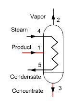
In a conventional single-effect evaporation cycle (Figure below) a product to concentrate (solute + solvent) is injected into a unit, heated by any heat input Q (steam 4-5). The concentrated product is extracted in 3, at the bottom of the unit, while the solvent vapor exits in 2 and is condensed, its enthalpy being lost.
Calling x the mass concentration of solute, equations governing the behavior of this unit are:
conservation of the total flow: m1 = m2 + m3
conservation of solute: x1 m1 = x3 m3
conservation of enthalpy: h1 m1 + Q = h3 m3 + h2 m2
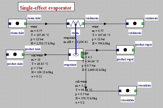
The figure below shows the synoptic view of such an evaporator modeled withThermoptim by external class EvapoConcentrator.java. In this example, there are 10 kg/s of feed product (salt water) containing 11% solids at 1 bar, that we want to bring to a concentration of 20% at 0.7 bar. It is necessary for this to provide heat in the form of 6.78 kg/s of saturated steam at 12 bar, which is fully condensed.
Multi-effect cycle
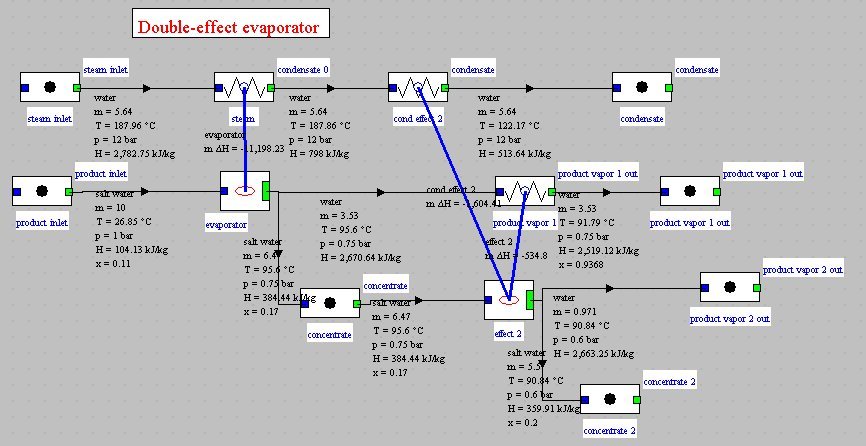
In a multi-effect (ME) cycle (Figure below), vapor produced is condensed in the evaporator of a second unit operating in series with the previous (the different types of irreversibilities by temperature heterogeneity, pressure drops etc. make it necessary to condense the vapor at a lower pressure and therefore temperature). A multi-effect concentrator thus allows recovering a portion of the solvent vapor and reduces the operation specific consumption.
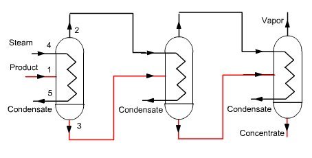
The figure below shows the synoptic view obtained for a double effect evaporator operating in conditions close to the previous (the pressure of the concentrate is 0.6 bar instead of 0.7). The flow of live steam, which was equal to 6.7 kg/s for single-effect system, is here 5.65 kg/s thanks to the use of vapor from the first effect for vaporizing part of the second. In the first case, ratio (steam evaporated)/(heating steam) is 0.66. In the second, it is 0.8.
Evaporative mechanical vapor compression cycle
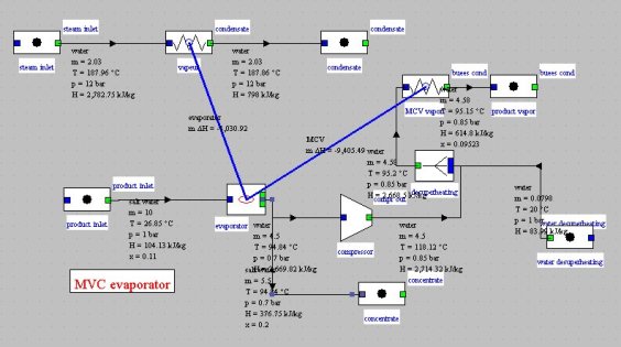
The figure below presents a modification of a single-effect evaporator at which was added a vapor mechanical compression for much of the heat supply. The input steam flow is divided by a factor greater than 3, while the compressor power is only 200 kW. Ratio (steam evaporated)/(heating steam) is 2.2.
Boiling point elevation
The saturated vapor pressure of a mixture (solute-solvent) decreases following Raoult's law. It follows that, at given pressure, the boiling point increases slightly compared to that of pure solvent. We call the boiling point elevation this temperature difference DTeb. Physically, the presence of the solute impedes the evaporation of the solvent, which may only be made at higher temperature.
It can be shown that DTeb is given by the following law:
DTeb = i x Keb / r
i is the solute van't Hoff coefficient, representing the number of elementary particles (ions etc.) formed in the solution;
x is the solute mass concentration;
Keb is the pure solvent ebullioscopic constant;
r is the solvent density.
The previous law ( indicates that the boiling point elevation is proportional to x. In practice, if we can assume that r and Keb are constant, an assumption valid for a small temperature range, it suffices to know some values of the boiling point elevation to identify it as:
DTeb = K x
An example of model of an externe substance with boiling point elevation is given in the model library. It has been used in the models previously shown.
DRYING BY HOT GAS
In previous section we introduced evaporation concentration facilities. Drying by hot gas is to evaporate the product by increasing the absolute humidity of the gas. There is thus also a separation of the solvent and solute which increases the concentration.
The hot gas must be clean enough to be placed in direct contact with the product to concentrate. It is generally air or gas turbine exhaust gases.
A particularly simple model allows us to get an idea of how such a facility works: it confines itself to establishing the mass and energy balances, assuming firstly that the fraction of the product flow which is extracted is known, and secondly, that only the hot gas provides the enthalpy corresponding to the evaporated water, taking into account heat loss from the component as a percentage of that value. Flow rates of both inlet streams are set by conditions upstream of the component and not recalculated. If the gas (here air) flow is insufficient for allowing its cooling to saturation to evaporate the water involved, a message warns the user.
The model we can choose is:
1. the only parameters are the fraction of the flow of product evaporated and the percentage of losses;
2. we first calculate the absolute humidity of the incoming gas, and determine the mass flow of dry gas from that of moist gas;
3. absolute humidity w at the outlet is determined, and we iterate on the outlet air temperature, which allows us to calculate the specific enthalpy. When the variation of air specific enthalpy is equal to that required to evaporate water, the solution is found (we neglect here the variation of sensible heat of water involved);
4. the composition of the outlet moist gas is changed;
5. values downstream of the node are updated.
Such a component can be easily implemented in Thermoptim as an external class, using moist properties calculation functions .
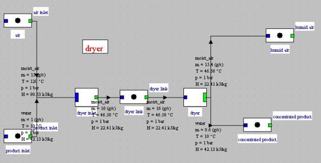
La figure ci-dessus montre le schéma Thermoptim d'un tel dispositif : un débit de 15 kg/s d'air chaud à 120 °C et très sec (e < 0,6 %) est mis en contact avec un flux de produit de 1 kg/s à 10 °C. 40 % de l'eau contenue dans le produit s'évapore, chargeant en humidité l'air qui se refroidit. En sortie du composant, l'état thermodynamique de l'air est donné figure ci-dessous : température de 50,7 °C, humidité relative de 40,7 %.
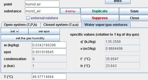
The figure above shows the Thermoptim synoptic view of such a device: a rate of 15 kg/s of hot and very dry air (e < 0.6%) at 120 °C is blown on a product stream of 1 kg/s at 10 °C. 40% of the water contained in the product evaporates increasing cooling air moisture. At the component outlet, air thermodynamic state is given in Figure below: temperature of 47.7 °C, relative humidity of 47.5%.
This air can then optionally be cooled and condensed then recycled if necessary.