Absorption cycles
Principle of absorption cycles
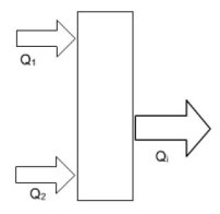
An absorption machine exchanges heat with at least three heat sources at three different temperature levels. Let us mark by index 1 the hot source, 2 the cold one and i the intermediate temperature source, and call W the work put into play in the machine and Delta S the entropy generation.
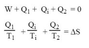
Writing the two laws of thermodynamics leads tothe following equations.
Two cases can be distinguished according to whether the temperature of the environment is or is not above the temperature of the cold source.
In the first case, which corresponds to the refrigeration cycle, the machine cools an enclosure at low temperature and rejects heat into the environment, Ti being greater than or equal to T0.
In the second case, which corresponds to the heat pump cycle, the machine extracts heat from the cold source (which may be the environment) and uses it to heat a chamber at intermediate temperature Ti.
Let us consider the first case, and assume that the intermediate temperature source is the environment, Ti being equal to T0.
Combining the previous equations, we get:
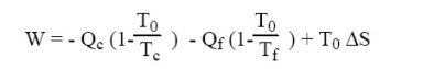
The first and the third term being negative and the second positive, this equation shows that work W may be zero, that is to say that it is possible to design a three-temperature machine for producing refrigeration cooling without consuming work. In practice however, many absorption chillers include circulating pumps.
The main interest of the liquid absorption refrigeration cycles is that they require only low power compared to their counterparts in mechanical vapor compression (less than 1%). Using a three-temperature thermodynamic cycle, they allow direct use of medium or high temperature heat to produce cooling, requiring little or zero mechanical energy input. As such, their theoretically total efficiency in terms of primary energy is greater than that of vapor compression cycles.
Moreover, they involve fluids whose impact on the ozone layer and the greenhouse effect is zero: ODP = GWP = 0. However, they require an input of heat at intermediate or high temperature, so that their indirect impact is not necessarily zero: it depends on the energy source used.
Another advantage of liquid absorption cycles is that they can be used in integrated energy facilities producing both mechanical power, heat at intermediate temperature and cooling. This is known as trigeneration, and total efficiencies obtained are extremely high.
Liquid absorption cycles involve at least two fluids: a solvent and a solute (the coolant). While other couples are studied, the only ones used in practice for almost all applications are the two couples LiBr-H2O and H2O-NH3.
Among the requirements for the prospective pair be appropriate, the solvent should firstly have a high affinity towards the solute, and secondly the latter should be much more volatile than the solvent so that the separation of the two components is optimal.
With the LiBr-H2O pair, water is the refrigerant, which imposes two constraints: first working pressures are very low given the saturation pressure law of water, and secondly the minimum cycle temperature must be greater than 0 °C. Machines using the lithium bromide-water pair are only used for air conditioning
LiBr-H2O absorption machine
A LiBr-H2O absorption machine is composed of eight main elements:
a desorber, which receives heat flux from the heat source, and wherein enters the strong solution at high pressure, preheated in solution exchanger (B). The exiting fluids are on the one hand, the almost pure refrigerant vapor (H2O) (C), and secondly the depleted solution (A);
the condenser, from which exits the vapor condensed and possibly sub-cooled (I), the heat removed being rejected in the surroundings;
a refrigerant expansion valve, which reduces the pressure of the refrigerant, exiting in the two-phase state at low temperature (L);
an evaporator where the refrigerant at low temperature and pressure is vaporized and possibly slightly superheated (J), extracting useful heat (refrigeration effect) from the cold source ;
an absorber, in which enters the vaporized refrigerant and the weak solution preheated in solution exchanger, and out of which flows the strong solution (D), the heat removed being rejected in the surroundings;
a solution heat exchanger, which allows for internal regeneration between the strong solution and the weak solution;
a pump which is needed to pressurize the strong solution before it enters the heat exchanger;
an expansion valve at the outlet of the heat exchanger which reduces the weak solution pressure to that of the absorber.
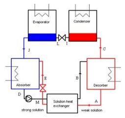
Note that the condenser, the refrigerant expansion valve and the evaporator work the same way as in a vapor compression refrigeration cycle.
Modeling of the cycle
To model such a cycle, we have created in the external model library two nodes which first involve the pair LiBr-H2O, whose properties are modeled in a particular external substance , and second exchange heat with outside: the desorber receives heat at high temperature and the absorber provides heat at medium temperature.
The representation of the thermal coupling is possible using two thermocouplers, called "heat input" and "cooling" in the diagram of the figure below: each external node calculates the thermal energy that must be exchanged, and each thermocoupler recalculates the "exchange" process to which it is connected.
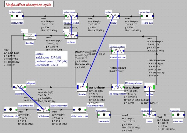
On the synoptic view of the figure above, we recognize in the central part the absorption machine, with the three sources with which it exchanges heat: above the cooling at medium temperature, at the bottom left the chilled water, and at the bottom right steam at high temperature.
In this synoptic view we counted the thecooling energy as useful energy a nd thermal energy supplied to desorber as purchased energy, which leads to a single-effect absorption cycle COP equal to 0.72
Exercises and personal activities
As an exercise you can model the cycle presented above. Its brief solution will provide the appropriate Thermoptim files.
References
ASHRAE, Fundamentals Handbook (SI), Thermodynamics and Refrigeration Cycles, 2001.
Fiches-guides de TD
Il n'y a pas de fiche-guide de TD traitant de ce cycle.
