Air conditioning
Rising living standards in industrialized countries has been accompanied by increasingly large demands in terms of thermal comfort conditions in residential and commercial buildings. Air conditioning has progressively developed in recent decades, leading to continued progress in the various disciplines that make up what is known as HVAC (Heating, Ventilation, and Air Conditioning).
To size an air conditioning system we must first be able to evaluate the thermal and water loads to import or evacuate. These loads depend on the climate and conditions of occupancy. They vary throughout the year and the design of an air conditioning system can only be made by taking into account these factors.
In this portal, we will only deal superficially with these issues. The interested reader should refer to the specialized literature, including ASHRAE publications.
Basics of an air conditioning system
An air conditioning system involves basic treatments that are presented in the pages on the properties of moist gas , to which we refer the reader for further developments:
mixers;
heaters;
chillers, with or without water condensation;
humidifiers, by water or steam;
dehumidifiers.
Technology
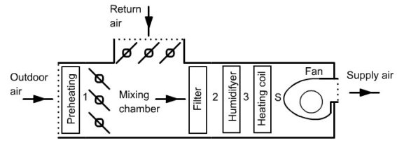
The figure below shows how looks like an air conditioning system and how it fits into a building.
The room is represented in the lower right. It has two sets of airflow veins, one for extraction and one for blowing. To cool the room, a certain air flow is "supplied" through vents. As this blown air mixes with room air, heat and water balance is achieved.
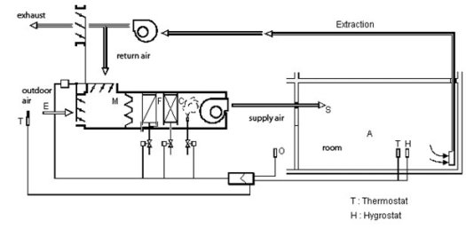
Supply conditions are determined so that this equilibrium corresponds to the desired comfort conditions.
Air extracted is partly discharged outside, and partly recycled, the recirculation rate depending on hygiene standards in force. Return air is mixed with fresh air, optionally preheated, the mixture being then "processed" so that its state corresponds to the supply conditions desired.
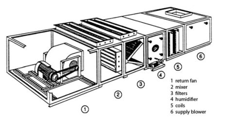
The figure below shows the cutaway of an air treatment vein set showing various boxes including a return fan, mixer, filters, humidifier, coils and a supply blower.
Design of an air conditioning system
The design of an air conditioning system comprises a series of distinct steps:
climatic conditions of reference that will be used to calculate the enthalpy and water loads must be first determined. In practice, it is based on climatic data published by national meteorological services, which are eventually corrected as indicated below. The values to take into account are not the extreme conditions but those likely to be reached or exceeded a few days per year on average. For winter, corrections must be made to temperatures at high altitude sites (- 1 °C every 200 m) and cities (+ 1 to 2 °C depending on the size of the metropolitan area), and an estimate of relative humidities can be obtained simply (100% along the coast or a lake, 90% elsewhere);
environmental conditions must then be defined (T. Agami Reddy, 2001). For specific industrial applications, refer to the information of AICVF Guides in France or ASHRAE in the U.S. For comfort cooling, it should be noted that most healthy people do not feel any noticeable difference as long as the relative humidity is between 30 and 60% and the temperature is below 25 °C. As a first approximation we can therefore choose for summer a temperature of 25 °C and a relative humidity of 60%, and for winter temperatures of 19 or 20 °C and a relative humidity of 30%;
once these values are chosen, it becomes possible to calculate loads. Depending on countries, calculations are slightly differently expressed: in the U.S. for example, sensible and latent loads are considered while in France we talk of enthalpy and water loads (AICVF, 1999). This simply means that in the first case, water to be extracted is directly converted in energy terms, while in the second it is expressed in kg/s;
the supply or condition line can then be determined by performing the appropriate balances. In the psychrometric chart, the condition line is the line of slope SHR or g passing through the point representing the desired comfort conditions. Each point of this line corresponds to a different supply flow-rate. The actual flow-rate value depends on various factors, such as the maximum allowable temperature difference to avoid any inconvenience (usually 6 to 12 °C according to the technique used), or the rate of mixing required (generally between 3 and 20 volumes/hour) to ensure good uniformity without drafts;
Once the supply point is determined, it remains to choose an air treatment for bringing a mixture of outdoor air and indoor air in this state. The recirculation rate depends on hygiene constraints. The more important it is, the higher the energy expenditure will be. The following examples show how basic treatments can be combined to form a proper air conditioning unit. Note that in first approximation the fan heats pumped air by about 1 °C. In winter this means less heating need, and in summer greater cooling need.
Examples of cycles
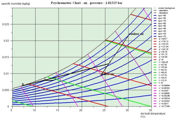
There are many possible air conditioning cycles. We will present only two examples of typical installations of summer cooling and winter heating in a guidance page for practical work. The corresponding cycles are plotted on psychrometric chart given below.
Link to the guidance page for practical work FG14 Air conditioning (in French): statement only , complete with solution.
Summer air conditioning
This facility is used to cool a large building like an airport located in a hot and humid climate.
The problem data are as follows: we seek to maintain the internal ambience of the building at a temperature of 24 °C and a relative humidity equal to 50%.
External climatic conditions are: temperature equal 30 °C , and relative humidity of 80%.
It is necessary to remove external and internal thermal loads of 162.6 kW, as well as a quantity of water equal to 60 kg/h, i.e. 0.01667 kg/s.
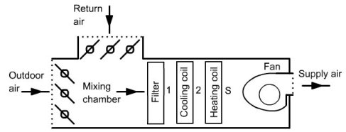
A possible treatment of the mixed air is to cool it, condensing water in excess to obtain specific humidity corresponding to the supply conditions, then warm it to supply temperature. The sketch of the cycle is given in the Figure below.
The plot of the cycle on the Carrier psychrometric chart is given in figure below.
Winter air conditioning
The facility is used to heat a large building like a bank, located in a cool, moist climate. For this, we have a ventilation system that allows air to blow in different parts of the building. For reasons of hygiene it is necessary to renew the air, but some can be recycled, however, which reduces heating needs.
So we recycle some of the indoor air that is mixed with outside air, previously preheated to prevent condensation on the ducts or jamming of registers. This mixture must be treated before being injected into the ventilation system so that its state corresponds to the supply conditions. These are calculated so that the external thermal loads are compensated by taking into account internal inputs. It is assumed that the water load is zero and air temperature is 27 °C.
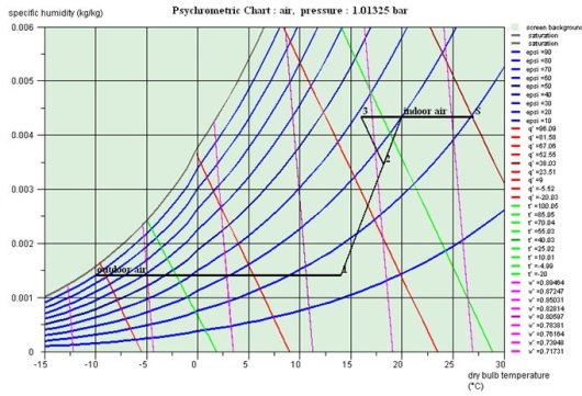
A possible treatment of the mixed air is to humidify it adiabatically until its specific humidity corresponds to the desired supply conditions and then to warm it up at the desired air temperature (Figure below).
The plot of the cycle on the Carrier psychrometric chart is given in figure below.
References
ASHRAE Fundamentals Handbook (SI), Thermophysical properties of refrigerants, 2001.
T. AGAMI REDDY, Psychrometrics and comfort, Handbook of Heating, Ventilation, and Air Conditioning, (Edited by J.F. KREIDER), CRC Press, Boca Raton, 2001, ISBN 0-8493-9584-4
S. K. WANG, Z. LAVAN P. NORTON Air Conditioning and Refrigeration Engineering, CRC Press, Boca Raton, 2000, ISBN 0-8493-0057-6.
CRC_pa_2
