

Kalina cycle
Kalina cycle
A Kalina cycle can produce mechanical power from a heat source at variable temperatures, such as effluent or exhaust gas from a gas turbine.
A Kalina cycle uses as working fluid water ammonia mixture, which has a large temperature glide.
As shown in Figure (b) below, the existence of this temperature glide reduces the average difference in temperature between the gas stream cooling in the HRSG and the working fluid as compared to what is happening in a Hirn cycle (Figure (a) below). Internal irreversibilities due to the temperature gradient are reduced.
One is therefore led to change the mixture composition between the hot zone (HRSG) and cold
zone of the cycle, which is achieved in the distillation and condensation system (DCS).
Let us recall that the thermodynamics of mixtures of real fluids is much more complex than that of pure substances. We advise those who are not familiar with these difficult issues to refer to this portal pages that deal with them.
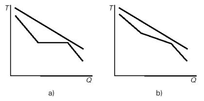
Internal irreversibilities in the Hirn (a) and Kalina (b) cycles
An elementary Kalina cycle (Figure below) consists of three main elements:
a recovery steam generator (HRSG);
a turbine;
a distillation and condensation system (DCS).
The complexity of the cycle results from two causes:
to benefit from a signifi cant temperature glide in the temperature range corresponding to the hot gas cooling, the ammonia quality of the mixture should be quite high (typically 50% NH3, 50% H2O);
to be condensed at a temperature above that of the surroundings and at low pressure, the ammonia quality of the mixture should be low (typically 20% NH3, 80% H2O).
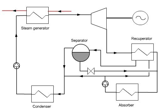
Kalina cycle
In the DCS the rich mixture leaving the turbine is cooled in a recuperator, then mixed with a weak solution of NH3 to raise the condensation temperature. The mixture (basic solution) is condensed in the absorber, recompressed and directed to the recuperator. A portion of the flow is used to dilute the rich solution leaving the separator, while the main stream is distilled at the recuperator outlet. The vapor is mixed with the extraction on the basic solution, condensed and compressed before entering the HRSG.
There are many Kalina cycle variants. The one presented here (Figure below) is relatively simple and easy to model, as long as we have functions for calculating the ammonia-water mixture properties, which can be done by Thermoptim connected to an appropriate external thermodynamic properties server. Mixer and separator nodes have been modifi ed to enable them to correctly calculate fl ow mixtures of different compositions for the first, and distillation of a mixture of known pressure and temperature for the second.
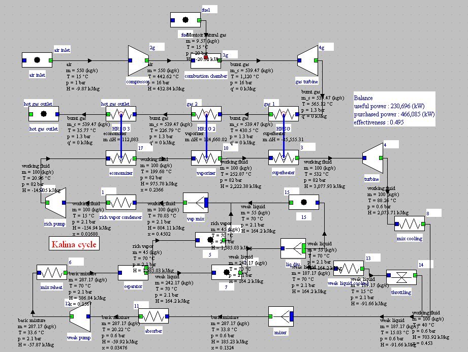
Note that the cycle parameter initialization is not trivial, mainly because the ammonia-water system compositions vary depending on the cycle points, coupled with the flow, heavily dependent on the pressure and temperature values. The values shown here are tentative and may change slightly from one setting to another.
At point 1, at the rich vapor condenser outlet, the working fluid is condensed at 2.1 bar and 15 °C :
Composition of the working fluid
It is a NH3-H2O mixture approximately equimolar (Figure below). It is pressurized in a pump and then vaporized in a boiler. At pressure of 82 bar, the bubble point temperature of the mixture is about 195 °C. Gradually, as boiling continues, the liquid phase ammonia quality decreases and the bubble point temperature increases to about 250 °C, then steam is superheated.
This steam is raised to 520 °C and then expanded in a turbine at the pressure of 0.6 bar and temperature of 88 °C. At this pressure and for the composition of Figure below, the dew point is very low and we cannot condense the expanded working fluid with a cold source at the surroundings temperature.
To circumvent this difficulty,the expanded working fluid is cooled down at 15 °C and mixed with a high flow rate of weak liquid
Composition of the weak liquid
Composition of the basic mixture
the basic mixture is then distilled, thereby separating the rich vapor and weak liquid
Composition of the rich vapor before mixing
a fraction of the weak liquid is remixed with the rich vapor to form the working fluid entering the turbine, which should not be too rich in ammonia if we want it to be condensed at room temperature;
the working fluid is condensed then pressurized and led to the boiler
the rest of the weak liquid is cooled and then expanded before being mixed with the working fluid.
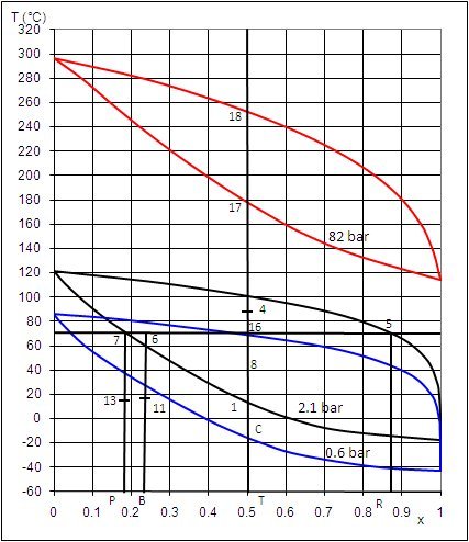
Representation of certain points on the ammonia-water mixture isobaric lenses allows one to
understand the changes in composition in the Kalina cycle (Figure below).
Plotted on this diagram are:
from bottom to top respectively, the three lenses at 0.6, 2.1 and 82 bar;
in the form of vertical segments from left to right, respectively, the ammonia compositions of the weak liquid (7-P), basic mixture (6-B), working fl uid (18-17-16-T) and rich vapor (5-R).
The working fluid leaves the turbine at point 4, at 0.6 bar. To condense it at this pressure, it should be cooled to point C, i.e. at about -18 °C, which is impossible by simple exchange with the surroundings.
The solution is to cool it to point 8, at 40 °C and mix it in an absorber with weak liquid subcooled at 15 °C (point 13). The mixture leaves the absorber at 19 °C with the basic mixture composition, in slightly subcooled liquid state. It can then be compressed to 2.1 bar at the cost of reduced work.
The heated basic mixture enters in state 6 the separator which operates distillation, separating weak liquid (7) and rich vapor (5). A fraction of the weak liquid flow is remixed with the rich vapor to form the working fluid at 2.1 bar (16), which is then condensed in the liquid state (1), thereby allowing to compress it up to 82 bar with a reduced work.
In the steam generator, the working fl uid is then heated in the liquid state to point 17 and then vaporized with temperature glide at point 18 and superheated at 532 °C (point outside diagram). It is then expanded in the turbine to point 4, closing the cycle.
Thermal integration of the Kalina cycle
The figure below show the shapes of composites for the Kalina cycle just described. It shows that the system can be balanced in terms of enthalpy: heat recovered during the cooling of the expanded steam and the weak liquid is enough to preheat the basic mixture before entering the separator
Thermal integration of the Kalina cycle is thus relatively simple.
The importance of the temperature glide and its impact on minimizing internal irreversibilities is very clear on these two curves. The Kalina cycle can recover much better the enthalpy available in the exhaust fumes than a conventional steam cycle.
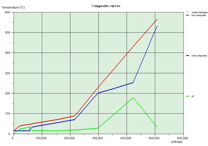
Composites of the Kalina cycle
Exercises and personal activities
An exercise is proposed. Its correction will provide the Thermoptim files allowing you to model the cycle presented above. Note however that this model requires to connect Thermoptim to an external library providing properties of the water-ammonia mixture.
References
Y. M. EL-SAYED, M. TRIBUS, A Theoretical Comparison of the Rankine and Kalina Cycle, 1985a, ASME publication AES-Vol. 1.
A.I. KALINA, Combined Cycle System with Novel Bottoming Cycle, Journal of Engineering for Gas Turbines and Power, vol. 106, pp. 737–742, 1984.
A.I. KALINA, Combined Cycle System with Novel Bottoming Cycle, ASME Journal of Engineering for Power, vol. 106, no. 4, Oct. 1984, pp. 737-742 or ASME 84-GT-135, Amsterdam.
A.I. KALINA, Combined cycle and waste heat recovery power systems based on a novel thermodynamic energy cycle utilising low temperature heat for power generation, ASME Paper 83-JPGC-GT-3, 1983.
M. JOHNSSON, J. YAN, Ammonia-water bottoming cycles: a comparison between gas engines and gas diesel engines as prime movers, Energy, Vol. 26, 2001, pp.31±44.
