Oxycombustion techniques
General
To conduct an oxyfuel combustion is to replace by pure oxygen the usual oxidizer, namely air, a mixture mainly of oxygen and nitrogen (respectively 21% and 78% by volume). Oxy-fuel technology allows at the same time to get fumes composed almost exclusively of water and carbon dioxide, and to drastically reduce emissions of nitrogen oxides. These are technologies already used in industry, including glass and steel.
The separation of CO2 and H2O is then easily done by simple water condensation, and the absence of nitrogen allows in addition NOx emissions and the volume of smoke to be greatly reduced.
The cycles efficiencies presented below are generally higher than that obtained by performing combustion with air, but we must not forget that they do not reflect the work involved in the production of pure oxygen, which must be taken into account in the overall balance.
Despite these advantages, these technologies have so far hardly been used for electricity generation, given the difficulties and costs involved in the production of oxygen. Several technical solutions exist, but the more developed today, called the Air Separation Unit, is to separate oxygen and nitrogen from air by cryogenic operation both costly and energy consuming.
Four oxycombustion devices using this separation technique have been recently proposed: cycles called “Water Cycle”, Matiant, “Oxyfuel” and Graz which are presented here.
Their principle is to use as oxidizer a gas containing on the one hand oxygen, and secondly a mixture of CO2 and H2O in different proportions depending on the case. Under these conditions fl ue gas thermophysical properties are similar to those encountered in a gas turbine whose oxidizer is air, which allows the use of existing high performance expansion turbines without the need to make further technological developments.
This process based on separation of the external air into oxygen and nitrogen is not the only one, and innovations are being considered in the form of internal separation cycles such as those based on use of:
membranes permeable to oxygen (AZEP cycle for which we propose a guidance page for practical work );
or transport of oxygen by chemical carrier by making, in the presence of air, a metal oxide which is then reduced before combustion (this is called Chemical Looping Combustion (CLC)).
Oxy-fuel cycle
In this combined cycle (Figure below), the oxidizer is a mixture of O2 and CO2. At the condenser inlet (6), we get fumes containing CO2 and H2O at a pressure of 1 bar. They are cooled by an external heat sink at a temperature low enough for almost all water to be condensed (7). The condensed water is extracted from the cycle.
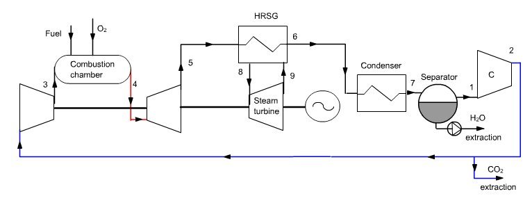
At the condenser outlet, a fraction of the gas composed mainly of CO2 is extracted (2), the remaining flow, equal to 35 kg/s in this example being compressed at the pressure of 40 bar in a compressor (2–3 ) before being mixed with pure oxygen (about 4.4 kg/s). This mixture is then used as an oxidizer in a stoichiometric combustion chamber (3–4) whose fuel is methane, the temperature at the end of combustion being about 1350 °C.
Fumes are expanded at 1 bar in a turbine (4–5), then cooled in a recovery steam generator (5–6) before entering the condenser, thus closing the cycle.
Un , travaillant entre les pressions de 0,03 bar et de 150 bars et 530 °C et mettant en jeu un débit d'eau de 10 kg/s, est couplé au cycle précédent pour former un cycle combiné.
A steam cycle, working between pressures of 0.03 bar and 150 bar and 530 °C, involving a water flow of 10 kg/s, is coupled to the previous cycle to form a combined cycle. In the diagram of Figure below, a simplified steam cycle is represented as a HRSG and the turbine pump and condenser are not shown nor oxygen and fuel compressors.
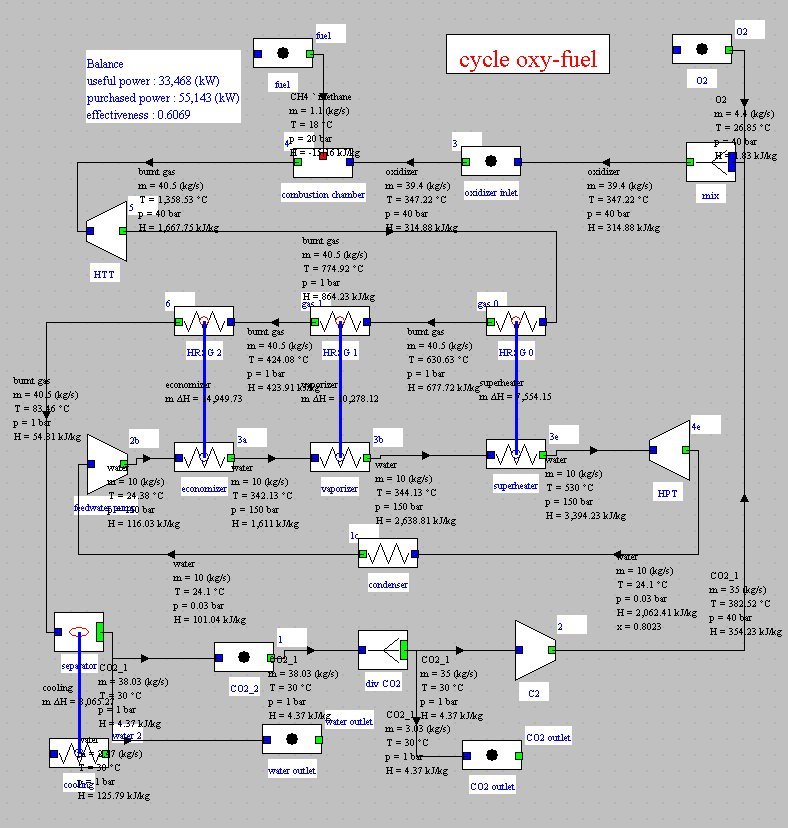
Synoptic view of the OxyFuel cycle
Water cycle
In this regeneration cycle (Figure below), the oxidizer of the first combustion chamber is a mixture of O2 and H2O, and expansion is sequential with intermediate reheat. At the condenser inlet (9), we get fumes containing O2 and H2O at a pressure of 0.1 bar. They are cooled by an external heat sink at a temperature low enough for almost all water to be condensed. The condensed water (1) is compressed at 4 bar (2), and the surplus to 125 kg/s is extracted from the cycle. At the separator outlet, the gas is composed mainly of extracted CO2.
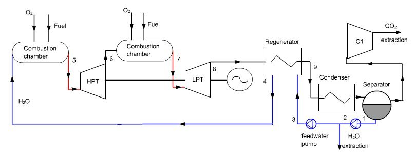
Liquid water is compressed at 83 bar (3) before it enters the regenerator (actually a steam generator), which it exits in the state of saturated liquid at 300 °C (4). Water is mixed with pure oxygen (about 33 kg/s), the mixture being used as oxidizer in a first combustion chamber (stoichiometric) whose fuel is methane, the end of combustion temperature being at about 900-1000 °C (5).
In modeling, one must be careful that it is impossible to mix oxygen with liquid water to form steam, because we do not have enough enthalpy in oxygen for the water vaporization. In reality, this energy is drawn from the available heat in the combustion chamber. We may either, as shown in Thermoptim diagram of Figure below, build a thermocoupler between the combustion chamber and the “vaporizer” process or model the whole as a combustion process followed by an exchange process designed to vaporize the water before mixing with oxygen.
The burnt gases are expanded in a high pressure turbine at the pressure of 8.3 bar (6), then mixed with pure oxygen (about 25 kg/s). This mixture is then used as an oxidizer in a second combustion chamber, also stoichiometric, whose fuel is methane, the end of combustion temperature being 1200 to 1300 °C (7). The fumes are expanded in a low pressure turbine at the pressure of 0.1 bar (8), then cooled in the steam generator, thus closing the cycle.
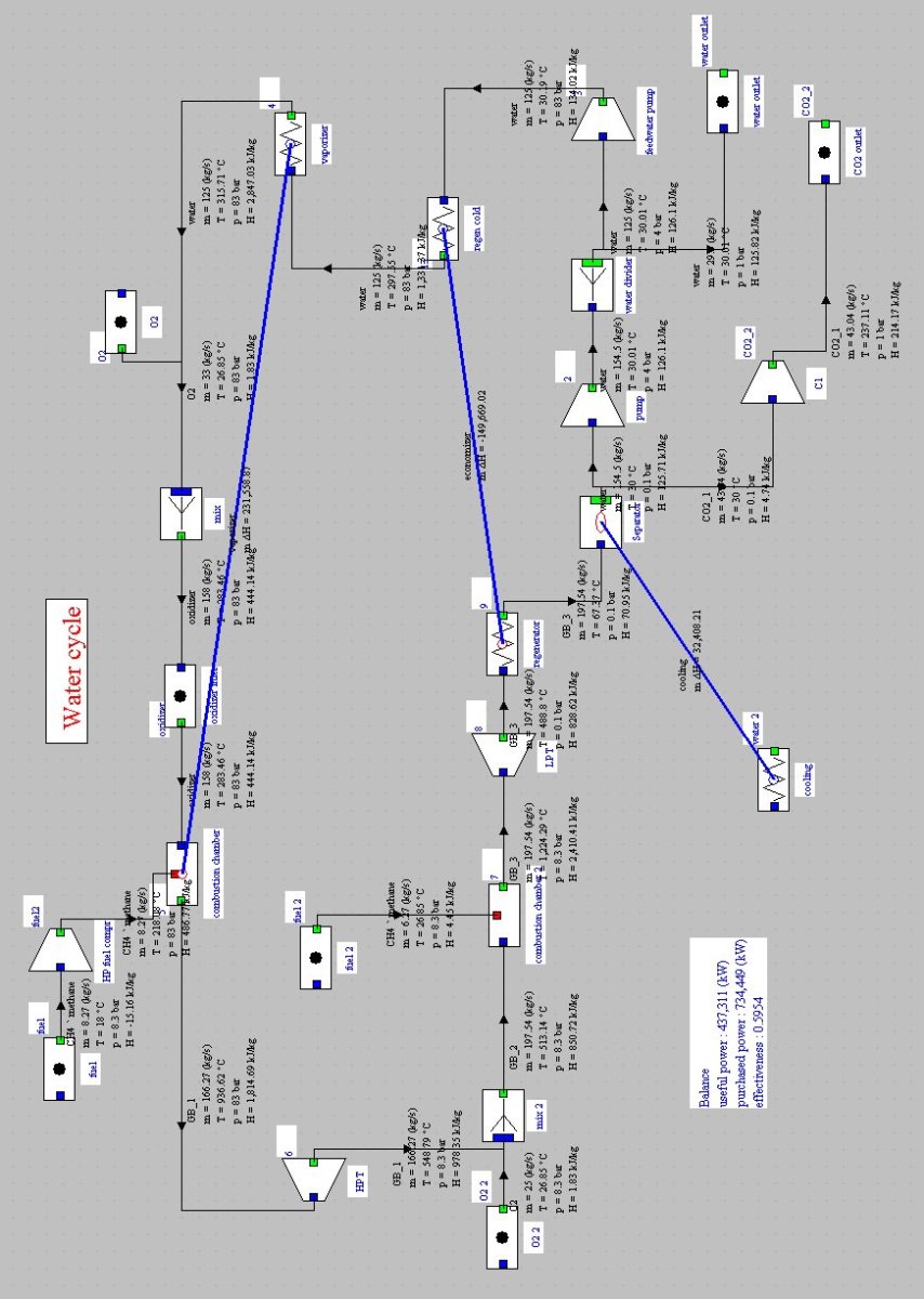
Synoptic view of the Water cycle
Graz cycle
In this cycle (Figure below), the oxidizer is a mixture of O2, CO2 and H2O, the latter two gases being mixed in the combustion chamber inlet, and then separated after expansion, each following a particular sub-cycle.
At the condenser inlet (11), we get fumes containing CO2 and H2O. They are cooled by an external heat sink at a temperature low enough for almost all water to be condensed. The condensed water is compressed at 12 bar (2e–3e), and the surplus to 110 kg/s is extracted from the cycle.
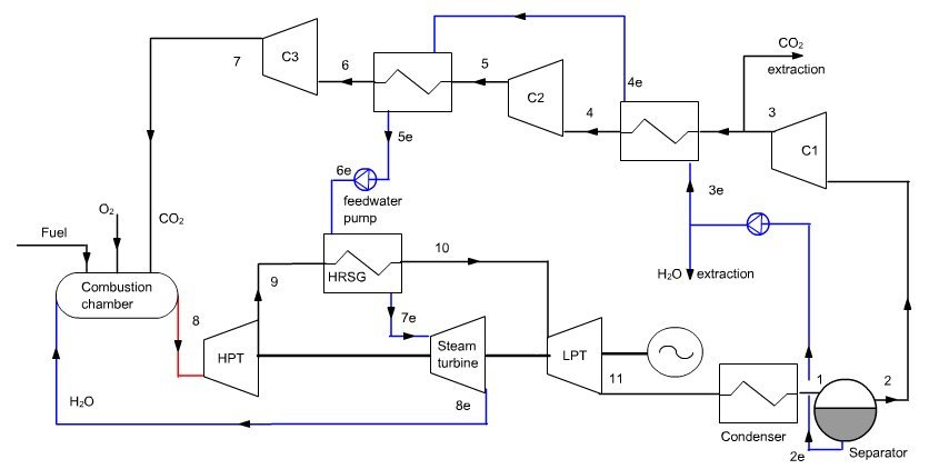
Cycle de Graz
At the outlet of the separator (2), gas composed mainly of CO2 at a pressure of 0.25 bar, is compressed (2–7) at the pressure of 40 bar in a three-stage compressor with intermediate cooling (C1, C2 and C3). A fraction of CO2 is extracted from C2, the remaining flow being equal to 200 kg/s. The intermediate cooling is by exchange with liquid water, which is compressed at 180 bar (5e–6e) before it enters the recovery steam generator (HRSG on the diagram), which it exits superheated at 560 °C (7e).
The gas at the outlet of C3 (7) is mixed with pure oxygen (about 0.5 kg/s) and steam from turbine “Steam turbine”, the mixture being used as oxidizer in the combustion chamber (stoichiometric) whose fuel is methane, the end of combustion temperature being equal to 1328 °C (8).
Burnt gases are expanded in a high pressure turbine (8–9) at the pressure of 1 bar and then cooled in the recovery steam generator (9–10). They are fi nally expanded in a low pressure turbine (10–11) at the pressure of 0.25 bar and then cooled in the condenser, thus closing the cycle.
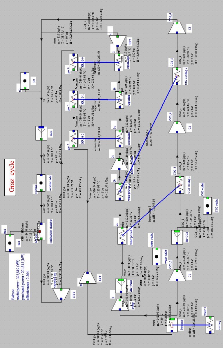
Synoptic view of the Graz cycle
Matiant cycle
In this regeneration cycle (Figure below), the oxidizer of the first combustion chamber is a mixture of O2 and CO2, and expansion is sequential with intermediate reheat. At point 1, a gas composed mainly of CO2, at a pressure we assume initially equal to 1 bar, is compressed at the pressure of 110 bar (2) in a four-stage compressor with intermediate cooling at 30 °C.
A fraction of CO2 is then extracted, the remaining flow, equal to 50 kg/s, being heated in a regenerator (3), before being mixed with pure oxygen (about 2.5 kg/s). This mixture is then used as an oxidizer in a first combustion whose fuel is methane, the temperature at the end of combustion being equal to 1300 °C (4).
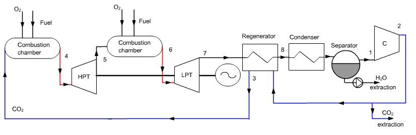
The burnt gases are expanded in a high pressure turbine at a pressure of 40 bar, then mixed with oxygen (about 5 kg/s). This mixture (5) is then used as an oxidizer in a second combustion chamber where the fuel is methane, the temperature at the end of combustion being equal to 1300 °C (6). The fumes are expanded in a low pressure turbine at the pressure of 1 bar (point 7), then cooled in the regenerator to point 8.
They are then cooled by an external heat sink at a temperature low enough for almost all water to be condensed. The condensed water is extracted from the cycle, while the residual gas enters the multi-stage compressor, closing the cycle.
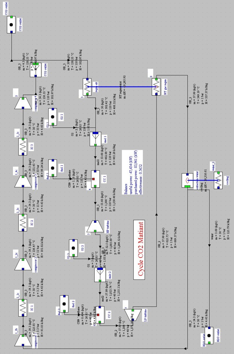
Synoptic view of the Matiant cycle
AZEP cycle
Sketch of the membrane
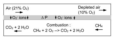
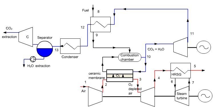
The AZEP cycle (Advanced Zero Emission Process) is a combined cycle involving internal separation of air through a membrane (Figure below). Air is sucked into the compressor of a modified gas turbine, where the combustion chamber is replaced by a chamber with two compartments separated by a ceramic membrane permeable to oxygen (Mixed Ionic-Electronic Conducting Membrane MIEC, Figure above). In one of the chambers, air is depleted in oxygen because of the difference in oxygen partial pressures between the two media. In the other, this oxygen acts as oxidizer for combustion of fuel in the presence of an inert gas that is but a recirculation of exhaust gases, composed mainly of CO2 and H2O, plus inert gases if the fuel contains some.
At high temperatures (above 700 °C), the ceramic membrane is a mixed ionic and electronic conductor, through which pass simultaneously O2- ions and electrons, oxygen being adsorbed on the surface.
Depleted air is expanded in a turbine (3–4), then used as a heat source (4–5) for a steam cycle (see Figure above, the pump and condenser not being shown in figure so as not to overload). The part of the flue gas not recirculated is expanded in a turbine (10–11), then cooled (11–12) either to preheat the fuel (8–9) or as a hot source for the steam cycle, before being condensed for water extraction (12–13). Remaining CO2 can then be captured. The part of flue gas that is recirculated is first cooled slightly by preheating air.
Much of the gas leaving the combustion chamber is recycled, in particular so that the average molar fraction of oxygen in the oxidizer is low enough that oxygen can pass through the membrane.
Exchangers around the ceramic membrane have not been shown. Although this is not the only possible solution, the steam generator can be split into two parts, one heated by the depleted air and the other by the flue gases.
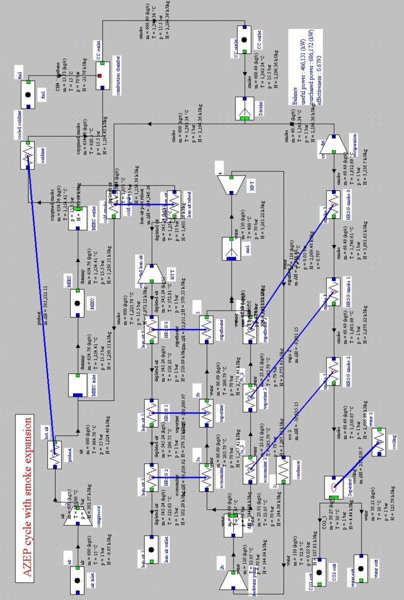
A guidance page for practical work shows how to model this cycle.
CLC cycle
The general principle of the CLC (Chemical Looping Combustion) cycle is close to the AZEP cycle: this is still a combined cycle, but air separation is accomplished through a chemical reaction allowing oxygen to be preferentially attached (Figure below).
Air (about 50 kg/s) is compressed (1–2) between 15 and 20 bar by the compressor of a modified gas turbine, whose combustion chamber is replaced by a chamber with two compartments between which circulates a metal oxide such as NiO, thanks to a circulating fluidized bed. In one of the chambers, air is depleted in oxygen (2–3) due to oxidation of the metal. In the other, the oxide is reduced and the oxygen released burns with a fuel (9–10).
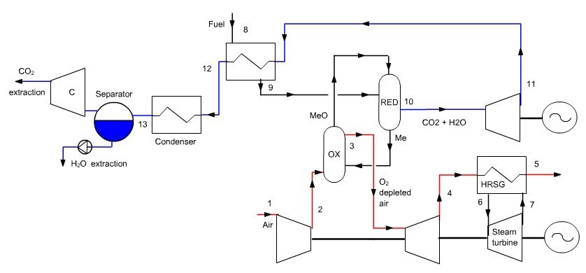
The depleted air (mole fraction of oxygen of about 0.14) is expanded in a turbine (3–4), then used as a heat source (4–5) for a steam cycle (6–7). The exhaust gases are also expanded in a turbine (10–11) and then used as heat source (11–12) on the one hand to preheat the fuel (8–9), and on the other hand (not shown in figure so as not to overload it) as hot source for the steam cycle, before being condensed for water extraction. The remaining CO2 can then be captured.
Although this is not the only possible solution, the steam generator can be divided into two parts, one heated by the depleted air and the other by the flue gases with a reheat.
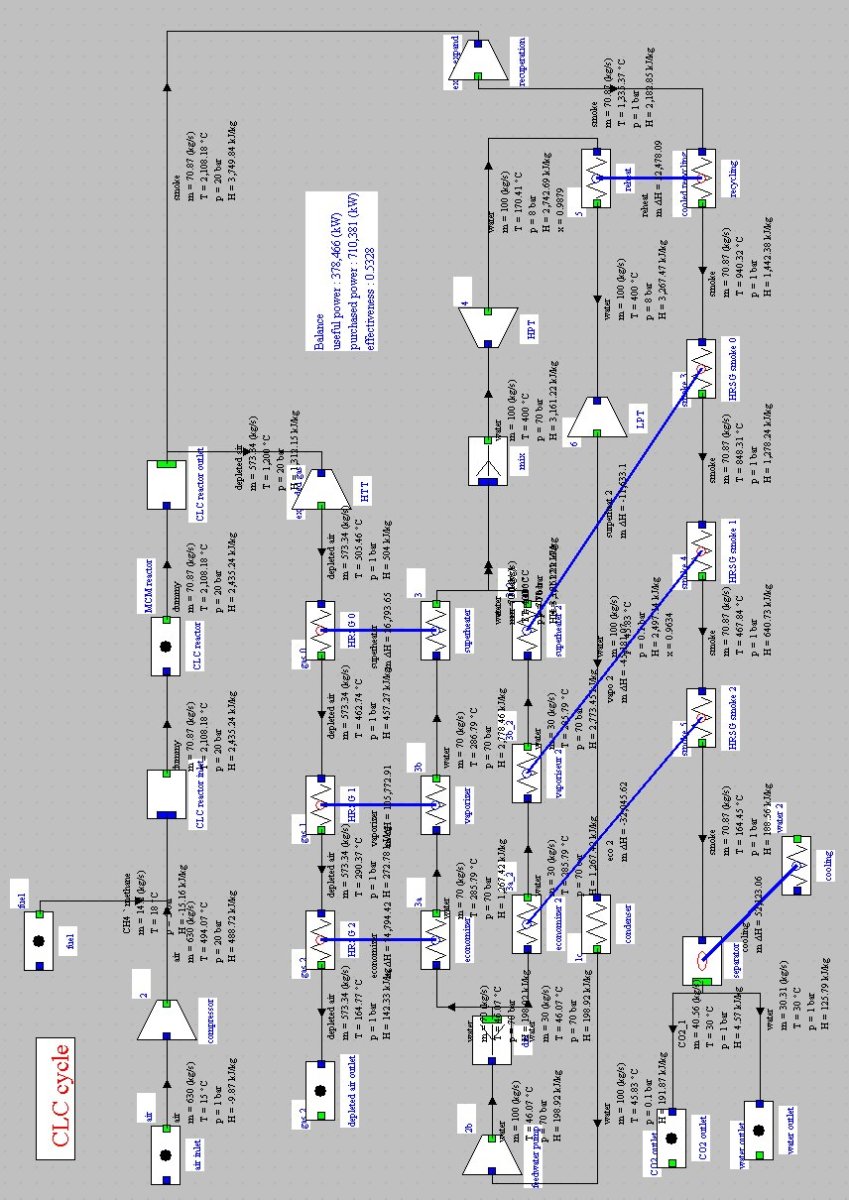
The reactor model which we used here should be refined. We assume that the temperature and the depleted air composition are known. It is thus possible to determine the flow of oxygen between the two reactor compartments.
Guidance page for practical work
The only guidance page for practical work on oxyfuel is related to the AZEP cycle .
Exercises and personal activities
Some exercises are proposed. Their correction will provide the Thermoptim files allowing you to model the cycles presented above ( Oxy-fuel , Water cycle , Graz , Matiant CLC ).
References
H. M. KVAMSDAL, O. MAURSTAD, K. JORDAL, AND O. BOLLAND, Benchmarking of gas-turbine cycles with CO2 capture, GHGT-7, Vancouver, 2004
BOLLAND O., KVAMSDAL H. M., BODEN J. C., A thermodynamic comparison of the oxy-fuel power cycles water-cycle, graz-cycle and matiant-cycle, Power generation and sustainable development (Liège, 8-9 October 2001), pp. 293-298,
Graz cycle site
