Pinch in a heat recovery steam generator (HRSG)
Introduction
Many researchers have addressed the problem of optimizing the recovery of sensible heat from an effluent. Exergy calculation does not pose any particular problem, but it turns out most of the time to be of little use because real efficiencies are well below the maximum theoretical values: the ideal reference is not appropriate.
Experience shows that the optimization of the steam cycle is often made at the expense of the heat recovery steam generator (HRSG). It is not enough to optimize each component to get a global optimum of the system: only a systemic optimization method can lead to a global solution.
Consider an effluent which may be gaseous or liquid, and a recovery steam cycle, simple without reheat. The following diagram illustrates the operation of a HRSG at the exhaust of a gas turbine, used as the hot source of a one pressure combined cycle.

Heat recovery steam generator (HRSG)
The left diagram shows the steam generator, consisting of three heat exchange zones: the economizer, the evaporator and superheater, and the right side shows, in a temperature - enthalpy (T , h) chart, the evolution undergone by the two fluids:
the gas stream, which is cooled;
the vapor, which heats up in the liquid state, is vaporized, then superheated.
Influence of the effluent temperature
Let us refine the representation in the enthalpy chart (figure below) .
The bold line represents, between points 1 and 2, the cooling of the effluent, from Tmax, maximum temperature, to Trej, exhaust temperature, and the dashed curve shows the heating of the water in the liquid state (economizer 3-4 ), its evaporation (evaporator 4-5) and the steam superheating (superheater 5-6).
The maximum superheat temperature is equal to Tmax - Tap, Tap being the approach.
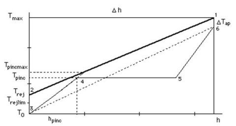
However, these are but idealized processes: strictly speaking, the changes do not exactly correspond to line segments due to the variation of the specific heat Cp as a function of temperature. Also, the various segments are not always continuously connected: approach between the economizer and the evaporator is generally set to about 10 K, in order to control the steam generator.
m being the mass flow,
 h = m Cp
T, and
T =
h/(m Cp). In this diagram, the slope of the curves is equal to the inverse of the heat flow mCp.
h = m Cp
T, and
T =
h/(m Cp). In this diagram, the slope of the curves is equal to the inverse of the heat flow mCp.
Trej must obviously be as low as possible for energy recovery to be maximized. However, Trej > T0 , the surroundings temperature. Furthermore, lower limits may exist for Trej related particularly, in the case where the effluent is a combustion gas (flue gas), as the possible condensation of gases may lead to the formation of acids (SO2 , NOx). These limits, which depend on the fuel used, can be relatively high (180-200 °C for heavy fuel oil, 130 °C for heating oil) or low (70 °C for natural gas).
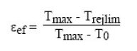
Calling Trejlim the effluent lower temperature limit, we can define:
firstly a maximum efficiency
 ef = (Tmax - Trejlim)/(Tmax - T0) for energy recovery, relative to the effluent and depending only on its nature;
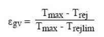
and secondly a relative efficiency of the recuperator
gv = (Tmax - Trej)/(Tmax - Trejlim).
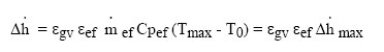
Recoverable enthalpy is:
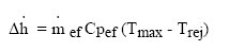
which can also be written as:
Influence of steam cycle pressure
To simplify the formalism, let us assume that the condensation (of steam after expansion) takes place at temperature T0. If this is not the case, the reasoning must be slightly modified while its foundations are not challenged.
A portion of the recovery steam cycle is shown in Figure 2 by the layout (3 - 4 - 5 - 6). The specific heat of the liquid being greater than that of the gas, slope 1/mCp is, for a single cycle without reheat, greater in the upper right portion (5-6 superheater) than that of the left part (3-4 economizer).
Furthermore, given the existence of the vaporization plateau (4-5 ), they are both greater than the average slope between T0 and Tmax - Tap shown in dashed lines. This results in the characteristic shape of the curve of the heat recovery steam generator (HRSG): the difference between the two curves decreases in the economizer, passes through a minimum, increases during vaporization, and then decreases again in the superheater. This is called the minimum pinch between the economizer and the evaporator at a temperature Tpinc equal to the saturation temperature at the pressure of the cycle.
We will say that this pinch, which must be strictly positive so that heat can be transferred from the effluent to the recovery cycle, is minimum (about 5 to 15 K) when its value cannot be reduced without affecting the proper operation of the installation. Already, very low values require large exchange surface, which may not be economically justified.
The steam flow-rate produced is dependent on the level of pressure, by the relations
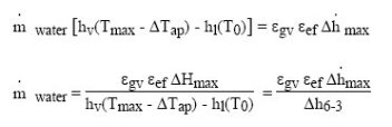
represents the change in enthalpy of the steam between points 3 and 6 of Figure 2.
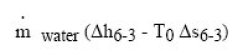
Calling in the same manner :
the variation of entropy of the steam, to maximize production of exergy of the steam, we must maximize:
i.e.
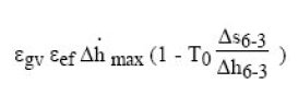
or:
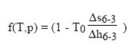
On the figure below, we see that f(T, p) is a monotonically increasing function of the pressure cycle, which means that it is advantageous to work at the highest possible pressure.
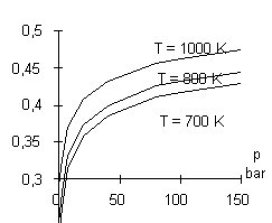
There is a limit, however, as shown in the enthalpy chart of Figure 2: the flow of steam (function of
h6-3) remaining substantially constant when the pressure of the cycle increases, the saturation temperature and therefore the amount of heat to be provided to the economizer increase, until the left bottom curve (economizer 3 - 4) intersects that of the effluent, for Tpincmax value. If the pressure increases beyond this limit, the pinch constraint can only be met if the effluent exhaust temperature increases, which leads to a decline in the relative effectiveness
gv.
The optimization of the steam cycle is then done at the expense of the energy recovery: the existence of a minimal pinch introduces a major constraint. As the diagram shows, the problem depends on many parameters: Tmax, Trejlim, Tap, Tpinc, and optimization of the complete system can be relatively complex.
The case presented above is obviously a textbook case, things being much more complicated in practice. However, the two concepts of pinch and exhaust temperature limit continue to play a major and interdependent role.
To illustrate this point, consider what happens, for a given pinch value, where the maximum temperature of the effluent varies.
Reasoning at constant enthalpy recovered and constant pinch and approach temperatures, the minimum pinch constraint is checked by the set of lines passing through the point P on the figure below. It is said that the effluent line pivots around the pinch point.
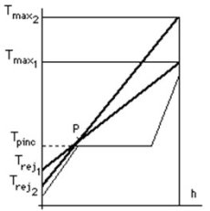
As can be seen in this figure, the higher Tmax, the lower Trej may be. We thus understand why the optimization of conventional power plants was not pinch controlled, especially since they typically use fuels whose minimum discharge temperature is high. However, when trying to recover energy on effluents, this constraint is all the greater as the temperature Tmax is lower.
This analysis shows that a single pressure steam cycle generally does not completely cool the effluent stream.
To improve the performance of the cycle, several steam circuits are used at different pressures (two, three or four).
The Figure below shows the value of using multi-level pressure: with some simplifying assumptions and a choice of scales, we can superimpose on an entropy chart the gas turbine and steam power plant cycles. In all three cases, the grey surface represents work provided for the same heat input in the gas turbine. The rectangle in the dashed line is the Carnot cycle
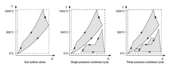
The optimization of such cycles is a complex problem, because to get the best cooling of the hot gas stream, there are many degrees of freedom on pressure levels, corresponding flow rates, and heat exchanger placement (in series or in parallel).
Conclusion
Energy recovery on effluents is a rather complex issue because of the existence of a pinch. It is impossible to independently optimize the recovery steam cycle, whether water or organic (ORC), and the recovery steam generator HRSG.
The optimization method of Thermoptim exposed in another page of this portal is one of the tools allowing one to deal with this kind of problem. It is the extension to the case of power or cogeneration plants, of the chemical engineering pinch method developed to optimize the configuration of very large heat exchanger networks (e.g. those of a refinery).
