Combined cycle, cogeneration or CHP
Introduction
We study here two high-performance hybrid energy systems: combined cycles and cogeneration plants.
Technological explanations are given in these pages :
Combined cycles
The excellent efficiencies reached today by combined cycle power plants (above 60% LHV), are the result of integration into a single production unit of two complementary technologies in terms of temperature levels: gas turbines, which operate at high temperature (in a aero-derivative turbine gases typically enter at 1300 °C in the expansion turbine, and come out at around 500 °C), and steam plants, which operate at lower temperatures (between 450 °C and 30 °C in this case).
We saw that regeneration can significantly increase the performance of the Brayton cycle, but the percentage of energy recovered is even lower than the temperature and pressure levels of this cycle are higher. In modern gas turbines, regeneration is rarely possible or economically worthwhile. Another way to enhance the residual enthalpy of the exhaust gases is to use them as a heat source for a second cycle of production of mechanical energy (Figure below). Combined cycles correspond to this new generation of thermal power plants.

The combined cycle thus obtained is a particularly successful marriage in the search for improved thermal performance: with currently available machines, efficiencies exceed 55% and are higher than those we can hope, even in the medium term, of the most advanced future steam plants.
In a simple combined cycle of this type, the gas turbine provides two-thirds of the total capacity. The steam turbine, fueled by superheated steam conditions of 85 to 100 bar and 510 - 540 °C, provides the remaining third.
The heat exchanger which ensures thermal coupling between the two cycles is called the heat recovery steam generator (HRSG).
The enthalpy exchange in a combined cycle can be summarized by the diagram in the figure below.

the gas turbine receives heat
 from the hot source. It provides on the one hand a useful work gt, and secondly a heat
 . The first term is the heat supplied to the steam cycle, the second losses;
the steam cycle produces useful work \taust, and the condenser rejects heat Qc.
Let us call
 the gas turbine efficiency,
 that of the steam cycle,
 that of the combined cycle, and ε the HRSG effectiveness, that is to say the ratio of
 to
to
 :
:


The combined cycle efficiency is equal to the sum of that of the gas turbine and the product of its complement to 1 by the HRSG effectiveness and the steam cycle efficiency.
For example, with
= 0.29,
= 0.32, ε = 0.83, we obtain
= 0.48.
This expression shows that it is as important to optimize the steam cycle as the recovery steam generator, and thus its effectiveness ε. Difficulties arise because the problem is highly constrained and there may be conflicts between these two objectives.
The optimization of such a combined cycle is based on the reduction of its internal irreversibilities, which can be grouped into three main categories: irreversibilities of mechanical origin, which take place in the compressor and turbines, irreversibilities of combustion, and purely thermal irreversibilities, related to temperature differences within the exchangers.
Much has already been done to limit mechanical irreversibilities, and the reduction of combustion irreversibilities is directly related to the maximum temperature of the fumes, which in turn depends on the resistance of the materials composing the combustion chamber and especially the first expansion stages of the gas turbine.
This question is the subject of guided exploration (C-M3-V1). Emphasis is placed on the setting of the internal exchanger which allows the residual enthalpy of gases leaving the turbine to be transferred to the steam cycle, and which is called a heat recovery steam generator (HRSG).
You will learn how to set a triple heat exchanger and study the concept of pinch.
Important note: to make this page easier for you to read, we have inserted here these guided explorations, but you should use the ones contained in the Thermoptim browser installed on your computer, because it is them that are coupled with Thermoptim and all the corresponding working files.
The figure below shows the synoptic view of this combined cycle
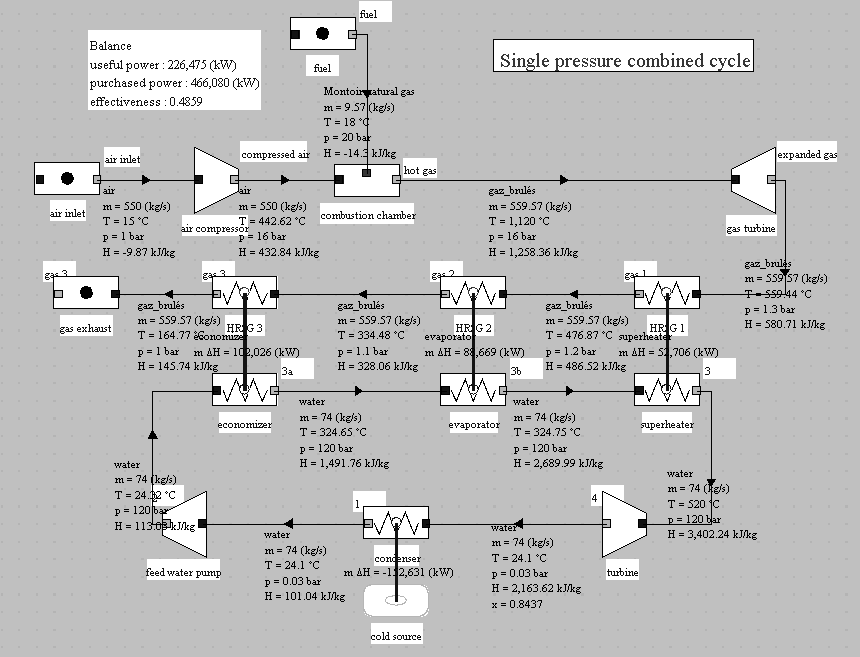
The hot gases come out of the gas turbine at 560 °C, and the maximum pressure of the steam cycle is equal to 120 bar. Under these conditions, it is impossible to cool the gases below 165 °C, which represents a significant loss.
Losses in the GVR and those in the exhaust are related. Their reduction therefore corresponds to an important issue. The ideal heat exchange would correspond to the case where the cooling curve of the gases and that of heating of the water are parallel. The exchanger would then operate against the current and irreversibilities would be minimal. This is unfortunately not feasible with water, and the single-pressure cycle has strong internal irreversibilities.
To improve cycle performance, several steam circuits are used at different pressure levels (two, three or even four).
The optimization of such cycles is a complex problem, because, to obtain the best cooling of the hot gas vein, there are many degrees of freedom on the pressure levels, on the corresponding flow rates, and on the placement of the exchangers (in series or in parallel).
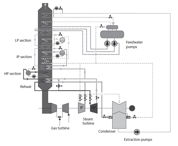
The figure below gives an example of an industrial three pressure HRSG, with the whole combined cycle.
Cogeneration
Cogeneration is the combined production of thermal energy and mechanical energy or electricity.
The basic idea of cogeneration is that combustions all take place at very high temperatures (above 1000 °C), while the need for heat in industry or for heating occurs at lower temperatures, usually between 80 °C and 300 °C.
Under these conditions, it is quite possible, when combustion is used to meet heat needs, to take advantage of this temperature difference to produce electricity via an engine cycle. It is enough for this that the hot source of the engine cycle is the boiler or the combustion chamber, and the cold source the heat needs.
The main advantage of cogeneration cycles is that they are among the most energy efficient.
Generally, the objectives pursued by cogeneration are twofold: on the one hand to achieve operational savings, and on the other hand to guarantee the security of electricity supply of at least part of the units.
Performance indicators
Let us call Qc the heat supplied to the cogeneration machine, that is to say, released by the combustion reaction, Qu the useful heat,
 the mechanical energy or electricity produced. In what follows, these different energies are expressed in the same units, usually kWh or MJ.
Let us call:
mechanical efficiency the ratio
 . It characterizes the performance of the facility as a generator of electricity. The best mechanical efficiencies are obtained in conventional power plants where Qu = 0.
overall efficiency the ratio
 . It characterizes, in terms of energy, the overall efficiency of the facility.
exergy efficiency the ratio
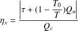 . T0 is the temperature of the environment and T is the temperature at which heat is provided. It allows, through the introduction of the Carnot factor, to characterize the temperature level at which heat is provided. Qc being the heat released in the combustion chamber, we assimilate it here to the exergy of the fuel.
heat-power ratio the ratio
 . It is representative of the distribution of energy between heat and electricity.
specific equivalent consumption the ratio
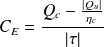
 being an average conventional boiler effectiveness, usually taken equal to 0.9. It represents the primary energy consumption leading to the production of one kWh of electricity. In fact, this is not quite the case, because heat provided Qc is final energy and not primary energy, which induces a slight bias. The indicative value of CE for a conventional power plant is greater than 2.5, when it is only 1.7 for a combined cycle plant of 60% efficiency.
These indicators, as defined above for a given operating point, are likely to vary depending on operating conditions, including the environment temperature. To estimate their average values over a long period, such as the heating season or a year, they are calculated from the cumulative values of variables considered.
The regulator has used some of them to determine if an energy facility may or may not be considered as a cogeneration unit, which determines its ability to sell electricity to utilities.
Two families of technologies
Technically, it is customary to classify CHP into two families, depending on the engine cycle used:
boiler and steam turbine systems, which are widespread, as the benefits of this configuration has been known for over a century. They can use a wide variety of fuels, including coal or waste;
internal combustion engine systems, which use either gas turbines or reciprocating engines (especially diesel and gas engines) . Heat is recovered from exhaust gases as well as coolants and lubricants. Only liquid and gaseous fuels can be used in these engines.
We shall confine ourselves to giving an example relating to this second category.
Industrial gas engine used in cogeneration (exploration C-M3-V2)
This guided exploration presents a cogeneration installation using the industrial gas engine that we modeled with a Beau de Rochas cycle in another guided exploration (C-M2-V5b).
Emphasis is placed on the calculation of the performance indicators of the cogeneration system.
You will learn how to set a thermocoupler.
The figure below gives an example of this cogeneration installation using a model E 2842 gas engine, manufactured by MAN Dezentrale Energiesysteme. The Thermoptim model is a variant of the one we presented when studying alternative internal combustion engines, by supplementing two cogeneration exchangers.
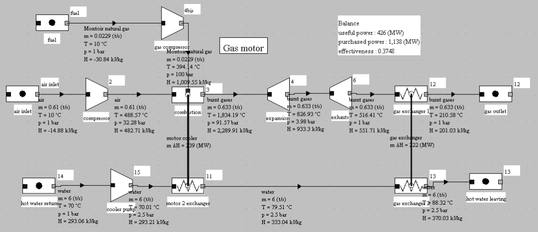
The coupling to the combustion chamber is carried out using a Thermoptim functionality that we have not yet used, that of a thermocoupler.
A thermocoupler allows components other than "exchange" processes to connect to one or more "exchange" processes to represent thermal couplings.
For a combustion chamber, the calculation is carried out in order to balance the thermal power transferred to the cooling fluid, itself defined by the combustion efficiency chosen.
In this example, its value is 0.79, which means that 21% of the power released by combustion is transferred via the thermocoupler (Figure below).
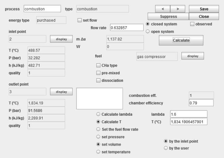
The screen of the thermocoupler (figure below) is similar to that of an exchanger, the exchange process appearing on the left of the screen under the name of "thermal fluid", and the combustion chamber on the right, under the name "process".
In this case, the user has only the choice between two calculation modes: either calculate the outlet temperature of the exchange process at a given flow rate, or calculate the flow rate, this temperature being known.
In this example, we have chosen to determine the outlet temperature, the flow rate of the coolant being known.
The thermal power communicated to the water is 239 kW.

