Introduction
We have seen that regeneration can significantly increase the performance of the Brayton cycle, but the percentage of energy recovered is even lower than the temperature and pressure levels of this cycle are higher. In modern gas turbines, regeneration is rarely possible or economically worthwhile.
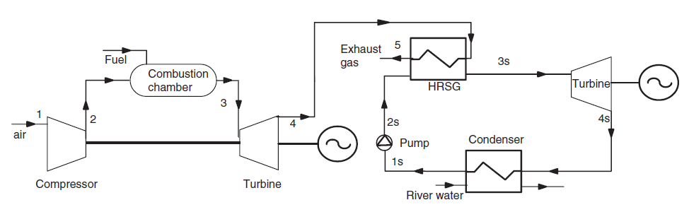
The combined cycle is the integration into a single production unit of two complementary technologies in terms of temperature level: gas turbines, which operate at high temperature and steam plants, which operate at lower temperatures (between 450 °C and 30 °C approximately).
Combined cycles correspond to this new generation of thermal power plants which enhance the residual enthalpy of the exhaust gases by using them as a heat source for a second cycle of production of mechanical energy.
The internal exchanger that transfers the residual enthalpy of gases leaving the turbine to the steam cycle is called the heat recovery steam generator (HRSG).
Heat exchanges in the HRSG
In a combined cycle power plant, the stream of hot gases exiting the gas turbine must be cooled by the water from the steam recovery cycle. In a single pressure level cycle, this water enters the exchanger in the liquid state at around 30 °C, after being compressed by the feed pumps located downstream of the condenser.
It is then heated in the economizer to the boiling temperature corresponding to its pressure. It is then vaporized, at constant temperature, then superheated, before being expanded in the steam turbine. This diagram represents the heat exchanges within the exchanger between hot gases and water.
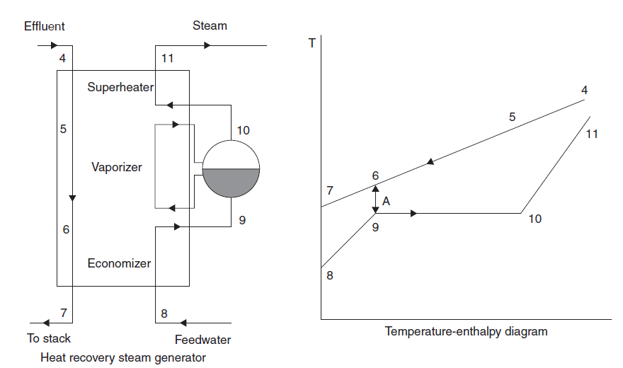
The associated enthalpy diagram shows that, if one imposes for technical reasons a minimum value of the pinches (temperature differences between the two fluids), between points 6 and 9 on the one hand, and between points 4 and 11 on the other hand, the heat exchanges are in fact made with much greater differences in almost all of the exchanger. This stems from the need to vaporize the water, which induces a very large "plateau" at constant temperature.
Losses in the HRSG and those in the exhaust are related. Their reduction therefore is an important issue. The ideal heat exchange would correspond to the case where the gas cooling curve and the water heating curve are parallel. The exchanger would then operate counter current and the irreversibilities would be minimal. Unfortunately, this cannot be done with water, and the single-pressure cycle has strong internal irreversbilities.
Loading the combined cycle model
Loading the model
Click on the following link: Open a file in Thermoptim
You can also:
- either open the "Project files/Example catalog" (CtrlE) and select model m10.1 in Chapter 10 model list.
- or directly open the diagram file (CC1P_En.dia) using the "File/Open" menu from the diagram editor menu, and the project file (CC1P_En.prj) using the "Project files/Load a project " menu from the simulator.
Model settings
In this section, we are mainly interested in the setting of heat exchangers.
Gas turbine setting (GT)
The setting of the gas turbine is similar to that of the previous directed explorations.
The sucked flow is equal to 550 kg/s, and the polytropic efficiency of the compressor and the turbine are worth 0.85, the turbine inlet temperature being set at 1150 °C.
We consider that pressure drops inside the HRSG account for 0.3 bar on the gas side.
With this setting, the temperature of the gases leaving the turbine is 580 °C.
Steam cycle setting
The pump ("feed water pump" process) flow rate is set, here equal to 74 kg/s.
The high pressure is 120 bar, and the superheat temperature 520 °C.
The steam turbine has an isentropic efficiency of 0.85, and the condensation pressure is 0.03 bar, which corresponds to a saturation temperature of 24.1 °C.
Steam generator settings
The pressurized water is brought to high temperature in the steam generator, the heating comprising the following three stages:
- heating of the liquid from around 24 °C to 323.4 °C, boiling point at 120 bar: evolution (2–3a) ;
- vvaporization at constant temperature 323.4 °C: evolution (3a–3b) ;
- superheating from 323.4 °C to 520 °C.
Let us examine how this triple exchanger is configured.
Pinches in exchangers
The minimum temperature difference between the hot fluid and the cold fluid is called an exchanger pinch. As a general rule, pinch values of the order of at least 5 to 10 °C are retained.
In the triple exchanger that constitutes the steam generator, check that the pinch is at the level of the evaporator.
Open the "evaporator" exchanger and determine the pinch value by calculating the minimum temperature difference between the hot fluid and the cold fluid.
What is the pinch value in the steam generator?
Overall performance of the combined cycle
With this setting, the combined cycle efficiency is 48.6%, and the mechanical power supplied is 226.5 MW.
Why it is important of modeling the GVR in the form of three exchangers
It is fundamental to model the HRSG in the form of three coupled exchangers, and not as a single exchanger, because the existence of the pinch between the economizer and the evaporator would then be masked.
To illustrate this point, we have constructed an erroneous model where the exchanger is modeled as a single exchanger.
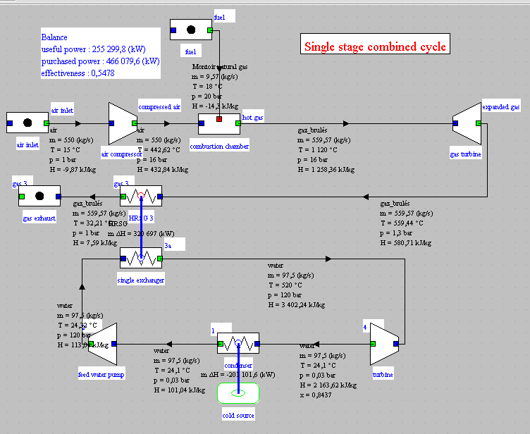
This model gives the illusion that the gases can be cooled down to 32 °C while maintaining the same pinch as in the right model.
The efficiency increases to 54.8% and the power to 255.3 MW.
These optimistic results are the consequence of the error on the modeling of the HRSG against which it is essential to be on guard.
This model is available if you want to load it. Its diagram and project files are called CC1_False.dia and CC1_False.prj.
Parametric study of the combined cycle
Exercise: study the influence of the high pressure and the flow of the steam cycle on the performance of the cycle, maintaining the same pinch value in the HRSG.
Decrease the pressure value of point 2, entering the value 100 bar, then recalculate the point and the "feed water pump" process.
Then recalculate several times in the simulator screen until the balance stabilizes.
You will notice that the efficiency and the power of the cycle decrease slightly, but that the pinch at the level of the evaporator has increased.
It is then possible to slightly increase the flow rate of the steam cycle in the "feed water pump" process, then to recalculate the project, until finding the initial pinch.
The performance of the combined cycle then increases, which shows that there are several couples (HP pressure, steam flow) which lead to fairly close results: the optimum is flat.
Conclusion
This exploration allowed you to discover a single pressure combined cycle modeled in Thermoptim.
This example shows that with a single pressure steam cycle, it is impossible to cool the gases below 163 °C, which represents a significant loss.
To improve the performance of the cycle, several steam circuits are used at different pressure levels (two, three or even four).
Their modeling poses no particular problem, but their optimization is a complex one, because, to obtain the best cooling of the hot gas stream, there are many degrees of freedom on the pressure levels, on the corresponding flow rates, and on the placement of the exchangers (in series or in parallel).
The design of such a cycle is facilitated with appropriate methodological tools, such as the pinch method.
We know the state of the water entering and leaving each part of the exchanger, as well as its flow rate, which are therefore set values.
Point 3a 3a is set at saturation temperature at the pressure of 120 bar, and its quality is equal to 0, to indicate the liquid state.
Point 3b is set analogously, except that the quality is 1, to indicate the state of vapor. An superheating of 0.1 °C has been taken into account to facilitate the calculation of the exchangers.
The flow rate and the inlet temperature of the hot gas stream into the superheater are known, and therefore set, which makes it possible to determine the temperature of the gas stream from the outlet point of this exchanger ("gas 1"), which is also the inlet point for the gas stream into the next exchanger, the evaporator.
Five quantities being known in this second exchanger, it can also be calculated, which makes it possible to find the temperature of the gas stream at the outlet point ("gas 2"), which is also the inlet point of the gas stream in the next exchanger, the economizer.
Step by step, the steam generator can thus be calculated.