

Reciprocating internal combustion engines
Introduction
We study here gasoline and diesel engines.
Technological explanations are given in this page.
There are two main types of reciprocating internal combustion engines:
spark ignition engines, whose principle was established by the French Beau de Rochas in 1860, and the first project carried out by the German Otto in 1876. Although some of these engines burn gaseous fuels, we will qualify them in the following by gasoline engines;
compression ignition engines, called Diesel, by the name of their German inventor who patented them in 1892.
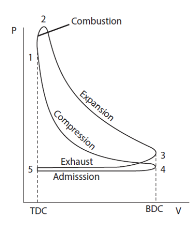
In four-stroke cycles, the most common, the head of the cylinder is pierced by two holes, controlled by valves, which put it in communication with the intake and exhaust manifolds. Note the difference with reciprocating compressors, where valves are not controlled, but opened by differences in pressure between the cylinder and these manifolds.
In two-stroke engines, exhaust occurs at the end of the expansion stroke through holes made in the side wall at such a level that they are unmasked by the piston at BDC. At the same time or shortly after, intake ports are opened which connect the cylinder with a manifold filled with fresh gas at a pressure slightly higher than that prevailing in the exhaust manifold.
The Diapason session S35-2t4t explains how these two kinds of engines operate
Theoretical and actual cycles
In its classic form, the elementary study of cycles is based on rather crude approximations: the working fluid is equated with air, itself equated to a perfect gas, and processes are considered perfect. To be more precise, we must consider:
the mass and the actual chemical composition of the working fluid, which varies according to the phases of the cycle, due to the introduction of fuel and combustion;
variations of the specific heat with temperature;
molecular dissociation at high temperature;
losses related to the renewal of the charge;
combustion kinetics;
heat exchanges between the working fluid and the engine walls;
mechanical friction and auxiliary consumption.
We begin by studying ideal cycles that lend themselves to easy thermodynamic analysis, and then we give guidance on how to take into account main non-idealities.
Although highly simplified, these cycles allow us indeed to draw some important conclusions that are not challenged by further analysis, such as those relating to the influence on engine performance of volumetric compression ratio, combustion conditions (constant volume, constant pressure), or the initial pressure in the cylinder, etc.
As we have just seen, the operation of these engines alternates phases in a closed system (closed valves) and in an open system (intake and exhaust), which has the effect of complicating their analysis. Their representation in a thermodynamic diagram is far from being as simple as that of the other cycles that we have studied.
Otto or Beau de Rochas cycle
Analyses of ideal cycles exclude intake and exhaust phases of two or four stroke real cycles. As a first approximation, the operation of gasoline engines can be represented by a cycle called Beau de Rochas or Otto, which is reduced, as indicated below, to four simple processes shown in the figure below in a Watt diagram:
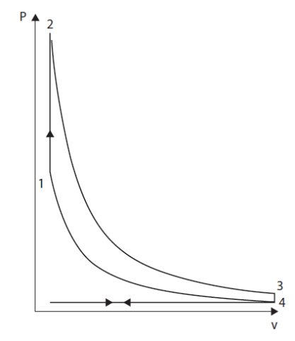
The first phase is a reversible adiabatic compression 4-1;
This compression phase in closed system begins after the inlet valves are closed and ends before ignition.
The second phase is a constant volume combustion 1-2;
Triggered at the end of compression, when the piston speed is zero, the combustion is supposed to be fast enough to be considered instantaneous, and therefore at constant volume, which is especially warranted in slow engines.
The third phase is a reversible adiabatic expansion 2-3;
This expansion in a closed system begins at the end of combustion and ends before the opening of the exhaust valves.
Finally, the fourth phase is 3-4 constant volume cooling.
By the end of expansion, opening the exhaust valve makes the pressure in the cylinder suddenly drop. It is assumed here that the discharge is instantaneous.
The figure below shows an example of such a cycle model for an industrial gas engine: model E 2842 gas engine, manufactured by MAN Dezentrale Energiesysteme.
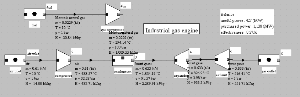
This cycle is the subject of guided exploration (C-M2-V5b).
Important note: to make this page easier for you to read, we have inserted here these guided explorations, but you should use the ones contained in the Thermoptim browser installed on your computer, because it is them that are coupled with Thermoptim and all the corresponding working files.
Diesel cycle
The fundamental difference between the diesel cycle and the Beau de Rochas cycle is the replacement of the constant volume combustion by combustion at constant pressure, as shown by Watt diagram of the figure below.
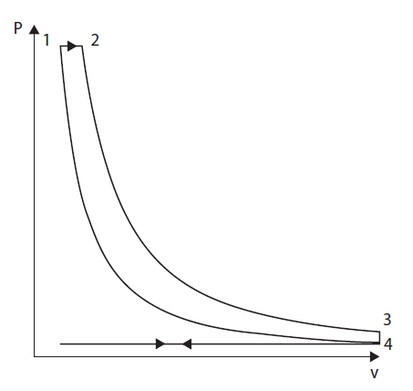
It is assumed here, hypothesis mostly valid for slow engines, that the expansion of gases due to combustion exactly compensates, in terms of pressure, the volume expansion due to the stroke.
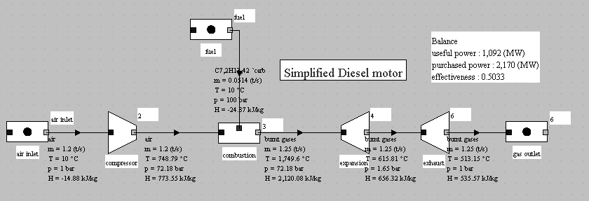
The model in the figure below represents such a cycle, with a volumetric compression ratio of 20 instead of 12. The efficiency is better than that of the gasoline engine following the Beau de Rochas cycle, but the gain comes mainly from the increased compression ratio.
This example highlights the important fact that the functions of components can differ from their geometric configuration. In the case of reciprocating internal combustion engines (gasoline or diesel), the same set of parts (the cylinder and the piston) successively plays the role of compressor, combustion chamber and then expansion device. The functional representation of such a system leads to connecting together three elements representing these different functions.
Actually, whether it is a gasoline or diesel engine, combustion takes place neither at constant volume nor at constant pressure, but appears as shown in the diagram in figure below. This difference is mainly due to the very high speed of rotation of most of these motors.
The Beau de Rochas and constant pressure diesel models that we have presented therefore deviate greatly from reality.
A better approximation can be obtained by considering that combustion takes place in three stages: it begins at constant volume, continues at constant pressure and ends at constant temperature. However, this model is also open to criticism (Figure below).
As a result, unlike the functional processes that we have studied so far, combustion in reciprocating internal combustion engines calls for at least three reference processes, which makes their thermodynamic analysis much more complex.

This model calls for some comments:
The intake charge includes ambient air and a fraction of recirculated gas coming from the dead space that still exists in the cylinder (3.3% by mass). Its composition is determined in the "inlet" mixer;
combustion takes place in three phases, as proposed by M. Thelliez (1989), the fuel being injected three times;
expansion occurs in two steps: in closed system between points 5 and 6, then in open system from 6 to 7 in valves and exhaust pipes.
This example shows how a Diesel engine cycle can realistically be modeled with Thermoptim. It is presented in the portal guidance pages number 20, as well as in the Diapason session 38.
Such a model is a little difficult to set, given its complexity.
Self-assessment activities
The following self-assessment activities will allow you to check your understanding of reciprocating internal combustion engines:
General mode of operation of a reciprocating internal combustion engine, gfe
Differences between gasoline and diesel engine, gfe
