Gas turbine cycles and variants
Introduction
After some reminders on combustion, we study here some variants of gas turbines: regenerative cycle, turbojet.
Technological explanations are given in this page.
Combustion Reminders
Previously, we talked about combustion but, to simplify things, we did not specify how combustion can be calculated, and, when we studied the model of the gas turbine, we replaced its combustion chamber by simple heating.
If you do not have a good command of this subject, we recommend that you refer to this page of the portal or follow this Diapason session on combustion.
Combustion gas turbine
Exploration of a gas turbine model with combustion
This cycle is the subject of exploration S-M3-V8-2
The objective of this exploration is to guide you in your first steps of modelling a combustion in Thermoptim.
Important note: to make this page easier for you to read, we have inserted here these guided explorations, but you should use the ones contained in the Thermoptim browser installed on your computer, because it is them that are coupled with Thermoptim and all the corresponding working files.
We will consider this cycle as a reference. It is called the Brayton cycle (Figure below).

Its setting is as follows: the turbine inlet temperature is 1150 °C, the high pressure is 16 bar, and the compressor and turbine are assumed to have polytropic efficiencies equal to 0.85.
The efficiency of this cycle is equal to 35.8%.
Let's examine the exchanges of this gas turbine cycle with its external sources in order to determine where the most important thermal irreversibilities are located.
On the hot source side, a fuel capable of producing fumes at more than 2000 °C is burned in the combustion chamber, but for technological reasons the turbine inlet temperature is limited to below 1200 to 1400 °C in terrestrial gas turbines. Higher values can however be reached in some turbojet engines. It is not possible to modify the cycle at this level.
On the cold source side, the release into the atmosphere of the gases leaving the turbine corresponds to a very high irreversibility. It is sometimes possible to reduce it.
The exhaust gases come out here at 533 °C, while the temperature of the air leaving the compressor is 443 °C.
Cycle with regeneration
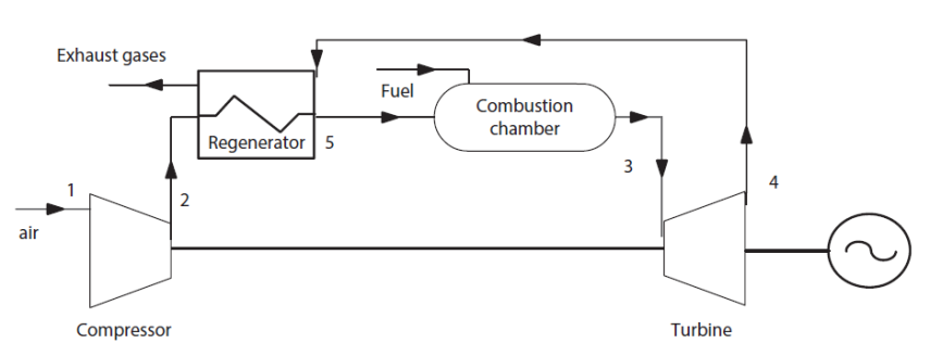
The exhaust gases exit at a temperature higher than that of the air leaving the compresso. It is therefore possible to partially heat this air before entering the combustion chamber, which further reduces fuel consumption. All you have to do is insert a heat exchanger between the exhaust gases and the compressed air.
This variant of the simple cycle is called regeneration cycle (Figure below).
We call regenerator effectiveness the ratio
 which characterizes the fraction of the available enthalpy actually recoverable.
The heat to be provided to the cycle is reduced in this case to (h3 - h5).
Introducing the ratio θ =
 of the temperatures at the inlet of the turbine and of the compressor, it is possible to plot the theoretical efficiency
 of this cycle as a function of the compression ratio r=
 , assuming that the working fluid is unique (air) and perfect.
The figure below shows the shape of the efficiency of the regenerative gas turbine for two values of effectiveness: 0.85 and 0.5. The four curves in each family correspond to different values of θ: 3, 3.5, 4 and 4.5.

We note that the interest of the regenerator is even better than the compression ratio is low. Indeed, beyond a certain limit, itself a function of θ, the fluid heating in the compressor is such that temperature T2' at the output of the compressor becomes higher than temperature T4' at the end of expansion. The regenerator can no longer function and becomes useless.
As shown in the graph of the figureabove, all curves corresponding to the same θ and different values of ε intersect at the point where T2' = T4'.
The results above are of course no more valid when we no longer assume that the working fluid is unique and perfect, but the existence of a limit remains true.
Exploration of a regenerative gas turbine
This cycle is the subject of exploration C-M2-V2.
In this guided exploration, you will start by studying the configuration of combustion in a simple gas turbine cycle, then you will be interested in the regeneration cycle.
Important note: to make this page easier for you to read, we have inserted here these guided explorations, but you should use the ones contained in the Thermoptim browser installed on your computer, because it is them that are coupled with Thermoptim and all the corresponding working files.
In the case of this gas turbine, the introduction of a regenerator with an effectiveness of 0.85 leads to the results shown in the figure below. The efficiency has increased and is now worth 39.5% instead of 35.8%.

The loss corresponding to the gases released in the atmosphere is smaller than before, but still the major source of irreversibilities, except for the combustion chamber.
Given that the current trend consists in increasing the compression ratio in gas turbines, regeneration is poorly suited for modern machinery using advanced technologies, except sequential combustion turbines. Instead, it is almost always used for small turbines (25-500 kW), called micro-turbines. We shall see later that combined cycles can valorize the residual enthalpy available in the exhaust gases when regeneration cannot be used.
Mechanical configurations
The simplest gas turbine is, as we noted above, a machine where the compressor and turbine are coupled on the same shaft, which directly drives the recipient machine.
An analysis of the transient operation shows that a single shaft turbine is poorly suited for operation at partial load, especially if the speed is set (as in electricity generation for example). However, in case of sudden discharge of the receiving machine, the runaway speed of the gas turbine will be low, the compressor absorbing, as we have seen, almost two thirds of the power supplied by the turbine.
The limits of adaptation of the single shaft turbine lead to the idea of separating it into two parts according to their respective functions: first the auxiliary turbine, usually located upstream, whose role is solely to drive the compressor, and second the useful power turbine, driving the receiver machine (Figure below). We can distinguish the gas generator, upstream, and the mechanical energy generator, downstream.
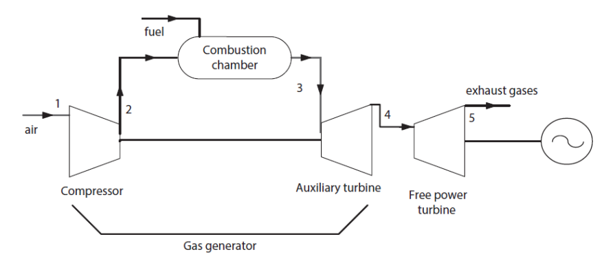
The gas generator being mechanically independent of the receiver machine, its speed can vary without constraint.
Aircraft propellers
For years, airplanes have been propelled by propellers driven by gasoline engines. Even today, this is the best solution for small airplanes. When, for larger aircraft, the propeller is kept in view of its excellent performance, it is often driven by a turboprop engine using an open cycle gas turbine. However, turbojet engines have replaced the propeller for the propulsion of many aircraft, including most long-haul airliners. It is also the only engine that is suitable for supersonic flight, and it thus equips mosty military aircraft. At very high speeds, and for the propulsion of long range missiles, the jet engine reaches its limits, and the ramjet is used because it provides very good efficiency. However, it cannot operate autonomously at take-off, which must then be provided by a turbojet or rocket engine.
A jet engine of the type that is commonly used in aviation is a simple modification of a gas turbine open cycle studied previously: the turbine is sizted to only drive the compressor.
At the turbine outlet, the excess energy available in the gas at medium pressure and temperature is converted into kinetic energy in a nozzle. The thrust results from the difference of momentum between intake and exhaust gases (Figure below).
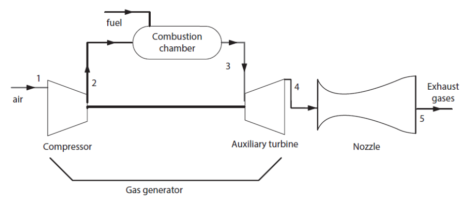
A turbojet is therefore the combination of a diffuser, a gas generator and a nozzle.
We speak of a gas generator because the function of the “compressor, combustion chamber and turbine” assembly is solely to generate hot gases at a pressure higher than ambient pressure, so that these gases can then be converted into kinetic energy in the nozzle.
It is quite possible to model with good precision various cycles of turbojets with Thermoptim
However, Thermoptim core components are not sufficient to build such models: to represent the inlet diffuser and the outlet nozzle, it is necessary to use two external classes, that is to say two extensions of the software package. Their classes are available in the model library.
The nozzle screen is given in the figure below. The upstream point corresponds to the outlet of the gas generator. Its pressure here is around 2.16 bar, and its temperature 864 °C.
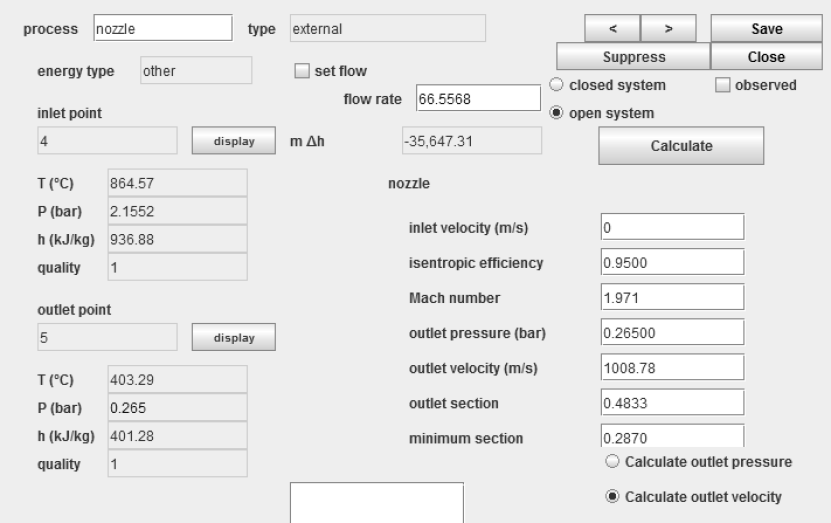
The downstream point is at an ambient pressure of 0.265 bar because the aircraft is aloft.
The right part of the screen includes the nozzle parameters. For the nozzle, two calculation methods are possible: to determine the outlet pressure knowing the outlet velocity, or to determine the outlet velocity knowing the outlet pressure, which is generally the case.
Model parameters are:
the gas inlet velocity (m/s), generally low;
the isentropic efficiency of the process (0.95);
either the gas outlet velocity (m/s), or the gas pressure at the exit of the nozzle, depending on the calculation option chosen.
The Thermoptim model of a simple turbojet engine is given in the figure below.

It also uses a diffuser component similar to the nozzle.
We may at first be satisfied with a simple model where we assume that we know the compression ratio and the flow passing through the machine, and polytropic or isentropic compressor and turbine efficiencies. Calculate the model then poses no particular problem.
This cycle is the subject of guided educational exploration (C-M2-V4).
Important note: to make this page easier for you to read, we have inserted here these guided explorations, but you should use the ones contained in the Thermoptim browser installed on your computer, because it is them that are coupled with Thermoptim and all the corresponding working files.
