Introduction
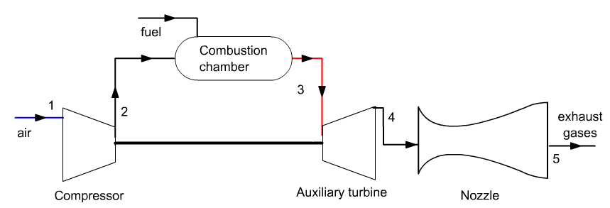
A turbojet engine of the type generally used in aviation is a simple modification of an open cycle gas turbine studied previously: the turbine is sized to only drive the turbochcompressor.
At the turbine outlet, the excess energy available in the gases at high pressure and temperature is converted into kinetic energy in a nozzle.
The thrust results from the difference of momentum between intake and exhaust gases.
The turbojet also includes an inlet diffuser, which is used to create a static precompression at the compressor inlet.
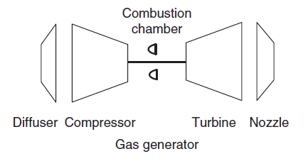
A turbojet is therefore the combination of a diffuser, a gas generator and a nozzle.
We speak of a gas generator because the function of the "compressor, combustion chamber and turbine" assembly is to generate hot gases at a pressure higher than ambient pressure, so that these gases can then be converted in kinetic energy into the nozzle.
It is quite possible to model with good precision various cycles of turbojets with Thermoptim.
However, Thermoptim core components are not sufficient to build such models: to represent the inlet diffuser and the exit nozzle, it is here necessary to use two external classes, i.e. two extensions of the software.
In this guided exploration, we will study the cycle of a single-flow turbojet engine..
Loading the single-flow turbojet model
We will now study the cycle of a single-flow turbojet engine.
Loading the model
Click on the following link: Open a file in Thermoptim
You can also:
- either open the "Project files/Example catalog" (CtrlE) and select model m9.4 in Chapter 9 model list.
- or directly open the diagram file (sfTurbojet.dia) using the "File/Open" menu from the diagram editor menu, and the project file (sfTurbojet.prj) using the "Project files/Load a project " menu from the simulator.
The settings of this model require a whole series of explanations.
Diffuser settings
Open the diffuser screen. In the diagram editor, the external processes are all represented by the same graphic component, but their screens can be partially defined by their designer according to their characteristics. This is what is done in the lower right part of their screen.
For a turbojet inlet diffuser, the three parameters to be defined are the speed of the aircraft (inlet velocity), the isentropic efficiency of the component, similar to that of a compressor, and the outlet velocity, assumed here to be zero.
Two calculation methods are possible: as here to determine the output pressure knowing the output velocity, or to determine the output velocity knowing the output pressure.
In our model, representative of an airplane in flight at an altitude of 10 km (pressure of 0.265 bar and temperature of - 51 °C), the entry speed is 222.22 m/s (800 km/h) that is to say a Mach number of 0.744, and the isentropic efficiency of the diffuser is worth 0.9. The air flow sucked in is 65 kg/s.
The overpressure produced by the diffuser is low: 0.1046 bar.
Compressor settings
The compressor is set in the following way, which differs from what we have seen so far: the compression ratio is no longer calculated as the ratio of the downstream pressure to the upstream pressure, but set at the value of 20, which means that the downstream pressure will be equal to 20 times the upstream pressure, which is that at the outlet of the diffuser.
Its polytropic efficiency is worth 0.9. Once this setting is defined, its calculation does not pose any particular problem.
Combustion chamber settings
There is no particular problem: Calculate lambda, the combustion temperature being known, and the downstream pressure being equal to the upstream pressure.
Turbine settings
The turbine setting is also specific: its power is just used to balance that of the compressor, and its downstream pressure is not known.
To do this, we use a feature that has not been used in the turbine screen until now: in its lower right part, there is a field allowing it to be mechanically balanced with a compressor. Double-click in the field just to the right of "mechanically balanced with", and select "compressor" from the list provided (which only includes this one element here).
Thermoptim will calculate the outlet pressure so that the two powers have the same absolute value, one being positive (that of the compressor), and the other negative (that of the turbine), taking into account sign conventions.
Of course, the polytropic efficiency of the turbine should also be specified, 0.9.
With this setting, the turbine outlet pressure can be determined: 2.39 bar, as well as the gas temperature: 891.5 °C.
Nozzle settings
The nozzle setting is as follows. It includes:
- the inlet velocity, assumed here to be 0 (this is the relative velocity at the turbine outlet)
- the isentropic efficiency of the component, similar to that of a turbine, here equal to 0.95
- the outlet pressure, here equal to 0.265 bar
Two calculation methods are possible: determine the outlet pressure knowing the outlet velocity, or as here determine the outlet velocity knowing the outlet pressure.
Thermoptim calculates the Mach number, the outlet gas velocity and the corresponding Mach number, the outlet section and the nozzle throttle section (minimum section).
Calculation of turbojet performance
Once the model is set, it becomes possible to calculate the engine performance.
The specific thrust, power and consumption related to the thrust are among the quantities most often used for this.
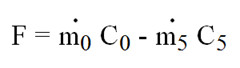
C0 being the speed of the airplane and C5 the velocity of the gases leaving the nozzle, the expression of the thrust is given by this formula, taking into account the variation of the flow rate through the engine due to the injection of fuel.
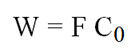
The power W is equal to the product of the thrust by the speed of the airplane.
These quantities are often expressed in a reduced manner, the thrust F being related to the air flow sucked (we speak of specific thrust), and the fuel flow at the thrust (we speak of specific fuel consumption).
Application exercises
Calculate the thrust of the turbojet
Calculate the specific thrust of the turbojet
Calculate the specific thrust (thrust relative to the air flow sucked in) from the information available in the different components of the model.
Calculate the power developed by the turbojet
Calculate the power developed from the information available in the various components of the model.
Calculate the specific fuel consumption of the turbojet
Calculate the specific fuel consumption (fuel flow compared to the thrust) from the information available in the different components of the model.
Conclusion
This exploration allowed you to discover a model of a single-flow turbojet engine and the specific settings it uses.
If you wish, you can study the influence of the compression ratio and the turbine inlet temperature on the performance of the turbojet engine.
Calculate the thrust from the information available in the different components of the model.