Introduction
One of the main source of losses in a gas turbine is the exhaust gas released from the turbine to the atmosphere while still at high temperature.
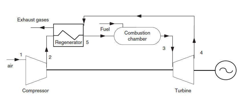
In a regeneration cycle, the compressed air is partially heated before entering the combustion chamber, which further reduces fuel consumption. All you have to do is insert a heat exchanger between the exhaust gases and the compressed air.
Gas microturbines, with a power of a few tens of kW, generally use this cycle. They are particularly used in cogeneration.
It is however clear that the regeneration can only be carried out if the turbine outlet temperature is higher than the compressor outlet temperature, which is not always the case.
In this guided exploration, we will start by studying the setting of combustion in a simple gas turbine cycle, then we will study the regeneration cycle.
Reference cycle
In the first part of this course (MOOC CTC-MS), to simplify things, we did not model the combustion. We only considered that the air leaving the compressor of the gas turbine was brought to the maximum temperature of the cycle in an exchange process.
To remedy this simplification, we will use the concepts of combustion which were presented in class.
The gas turbine sucks air at 25 ° C and 1 bar, and compresses it to 16 bar in a 0.85 isentropic efficiency compressor.
The compressed air enters the combustion chamber burning natural gas, then the burnt gases are expanded in a 0.85 isentropic efficiency turbine.
The turbine inlet temperature is 1065 °C and combustion is assumed to be perfect.
Loading the reference model
Click on the following link: Open a file in Thermoptim
You can also:
- either open the "Project files/Example catalog" (CtrlE) and select model m9.1 in Chapter 9 model list.
- or directly open the diagram file (GT_ref.dia) using the "File / Open" menu from the diagram editor menu, and the project file (GT_ref.prj) using the "Project files/Load a project " menu from the simulator.
The setting of the gas turbine being analogous to that which you studied in guided exploration S-M3-V8, except for combustion, we will only be concerned here with this component.
In the diagram editor, the combustion process is represented by a combustion chamber component comprising two processes at the inlet, the oxidizer, here air at the compressor outlet, connected to the blue port on the left, and the fuel connected to the red port located in its upper part.
The burnt gases exit from it through the green port on the right, here connected to the turbine.
Combustion settings
Open the process "combustion chamber".
The state of the inlet and outlet points is recalled on the left of the screen, as with any process. The link to the fuel appears under the "Calculate" button. If you click on "display", the screen of the process defining the fuel opens, giving you access to the point defined by the fuel and its state variables, here pressure of 20 bar and temperature of 15 °C.
Fuel is a compound gas whose composition corresponds to natural gas as it is available at the Montoir de Bretagne LNG terminal, in Loire Atlantique, France.
The combustion settings are defined in the lower right part of the process. Here, we have chosen the option "Calculate lambda", the combustion temperature being set at 1150 °C. Recall that lambda is the air factor as it appears in the combustion equation.
In addition, the combustion chamber is assumed to be isobaric, ("set pressure" "by the inlet point"), which means that the outlet pressure will be equal to the inlet pressure. If the option "by the user" had been selected, the pressure of the outlet point would not have been modified by the calculation, the value entered by the user being considered the correct one.
Please note that the substance at the outlet of a combustion chamber must be an unprotected compound gas, so that Thermoptim can modify its composition.
You can access this composition from the outlet point screen.
Loading the regenerative turbine model
We will now study the regenerative cycle.
Loading the model
Click on the following link: Open a file in Thermoptim
You can also open the diagram file (regen_GT.dia) using the "File / Open" menu from the diagram editor menu, and the project file (regen_GT.prj) using the "Project files/Load a project " menu from the simulator.
The efficiency is 39.43% instead of 35.8% without regeneration.
Model settings
As we have indicated, the new model implements a new component, the regeneration exchanger, called "regenerator" and placed between the exhaust gases and the compressed air.
Let us take a look at its settings.
Determine the pinch value by calculating the minimum temperature difference between the hot fluid and the cold fluid.
What is the value of the pinch in the "regenerator"?
Limits of regeneration
For regeneration to be used, the turbine outlet temperature must be higher than the compressor outlet temperature.
However, this criterion mainly depends on two factors: the compression ratio, and the turbine inlet temperature.
A second factor conditions the interest of regeneration: the effectiveness of the exchanger.
Application exercises
Influence of compression ratio
See by yourself how the compression ratio affects regeneration possibilities.
Start by returning to the initial setting and enter 0.85 as the regenerator effectiveness before recalculating it.
Then increase the compression ratio by changing the pressure in point 2 at the outlet of the compressor process, then recalculate the point first, then the process.
Finally recalculate several times in the simulator screen until the balance stabilizes.
Influence of the turbine inlet temperature
Study by yourself the influence of the turbine inlet temperature on the regeneration possibilities. To do this, start by returning to the initial setting and enter 16 bar in the screen for point 2 before recalculating the point and the compressor process.
Then reduce the combustion temperature in the combustion chamber, and recalculate the process.
Finally recalculate several times in the simulator screen until the balance stabilizes.
Conclusion
This exploration allowed you to familiarize yourself with a combustion screen, to discover a model of regenerative gas turbine, and to analyze the sensitivity of this model compared to some of its operating parameters.
Open the "regenerator" heat exchanger.
It ensures the coupling between two exchange processes called "regen air" and "regen gas".
The known quantities are the two flow rates of the fluids, as well as their temperatures at the inlet of the exchanger, ie a total of four constraints.
We must therefore set a fifth constraint, which we have chosen to be the effectiveness of the exchanger, assumed here to be equal to 0.85.
Recall that the effectiveness epsilon of an exchanger is defined as the ratio of the largest temperature increase within the fluids to the difference in the inlet temperatures of the two fluids.
Now change its value by entering 0.7 instead of 0.85, then recalculate the exchanger.
Then recalculate several times in the simulator screen until the balance stabilizes.