Variants of steam power plants
Introduction
We study here some variants of conventional steam power plants: reheat and regenerative cycles, Pressurized Water Reactor PWR plants.
Technological explanations are given in these pages :
Reference cycle settings
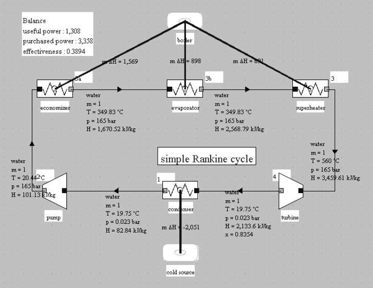
The reference cycle that we will use for steam power plants is a variant in terms of settings of that presented in the first part of the Lightweight presentation course: the low pressure is set at 0.023 bar, the high pressure at 165 bar, and the superheat temperature is 560 °C, as shown in the synoptic view of the figure below. Its efficiency is 39%.
Let us calculate for this cycle the value of Carnot's effectiveness, with Tc = 15 + 273.15 = 288.15 K and Th = 1000 + 273.15 = 1273.15 K:
 = 78 %. The actual efficiency is therefore close to 50% of the maximum theoretical efficiency.
Reheat steam power plants
As we have seen above, it is possible to improve such a cycle by using staged compressions and expansions.
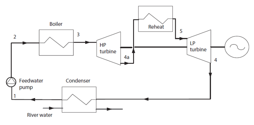
A first idea to improve the Rankine cycle is to approach the Carnot cycle by conducting reheats. In this case, we begin by partially expanding the steam, then it passes again into the boiler, where it is heated, at the new pressure, at the maximum cycle temperature (Figure below). This operation can optionally be repeated several times.
The result is an increase in power and efficiency of a few percent.
The figure below shows the cycle plot in the (h, ln (P)) chart. We have superimposed the new cycle in bold and the simple cycle in thin lines.
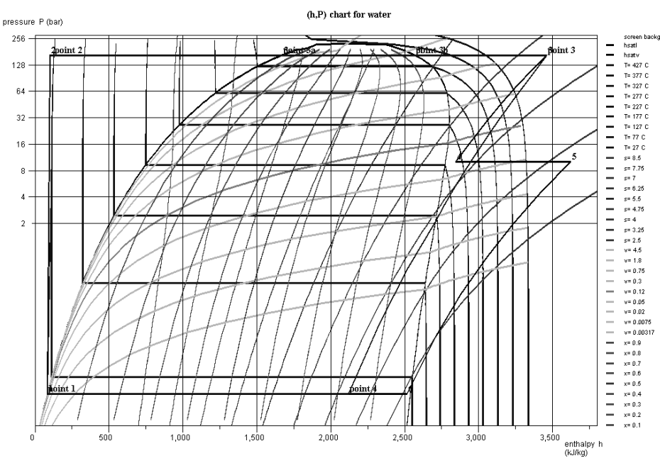
One can observe a clear increase in the quality at the end of expansion, which is always interesting to extend the life of the turbine blades, for which liquid droplets are abrasive.
The price however is a higher complexity, but as the expansion must be staged anyway, this improvement has no major technological impact on the power plant.
Guided exploration C-M1-V3 below will explain how to set up such a cycle. However, we will start by introducing an important new concept, complementary to that of isentropic efficiency.
Polytropic concept
Recall that, for a turbine, the isentropic efficiency is defined as the ratio of the actual work provided by the turbine to the work it would have provided if the adiabatic expansion was perfect.
Note that knowing the isentropic efficiency
 provides no indication of the law followed by the fluid during the irreversible expansion. To know this law, you have to give yourself additional hypotheses.
One of the most common leads to the widely used notion of polytropic, which can cover slightly different definitions depending on the authors.
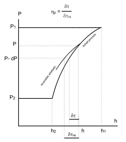
The hypothesis here is to consider that irreversibilities are uniformly distributed throughout the expansion, which amounts to supposing that, during any infinitely small stage of the process, the isentropic efficiency keeps a constant value, by definition equal to the polytropic efficiency
 which thus appears to be an infinitesimal isentropic efficiency (Figure below where
 is the work value for the reversible adiabatic).
We can then show that, for a perfect gas, the law of the process followed by the fluid is of the type
 , but it is not as simple for a vapor.
For multi-stage machines with large numbers of similarly constructed stages, such as a steam turbine, this efficiency has a clear physical meaning: it is, in a way, the isentropic efficiency of a stage.
Modeling a multi-stage turbine according to a polytropic approach is therefore more realistic than assuming that its isentropic efficiency is constant whatever the expansion ratio.
Knowing the polytropic efficiency of the machine and the expansion ratio, it is possible to determine the isentropic efficiency of the machine.
Self-assessment activity
Although they can be to a large extent considered as equivalent in a large number of cases, the polytropic approach is generally preferred to model the compression or the expansion in a multistage turbomachine, as the polytropic efficiency can be considered as an elementary stage isentropic efficiency.
It is particularly appropriate to do so if you make sensitivity analyses varying the compression or expansion ratio.
This is why gas turbine compressors and turbines are generally modeled using the polytropic reference.
The following self-assessment activity will allow you to check your understanding of the polytropic efficiency:
Reheat steam power plant settings
This cycle is the subject of guided exploration (C-M1-V3).
This exploration shows how the simple steam cycle can be improved, the objective being to minimize irreversibilities.
You will learn how to set a compression or expansion process according to a polytropic law.
Important note: to make this page easier for you to read, we have inserted here these guided explorations, but you should use the ones contained in the Thermoptim browser installed on your computer, because it is them that are coupled with Thermoptim and all the corresponding working files.
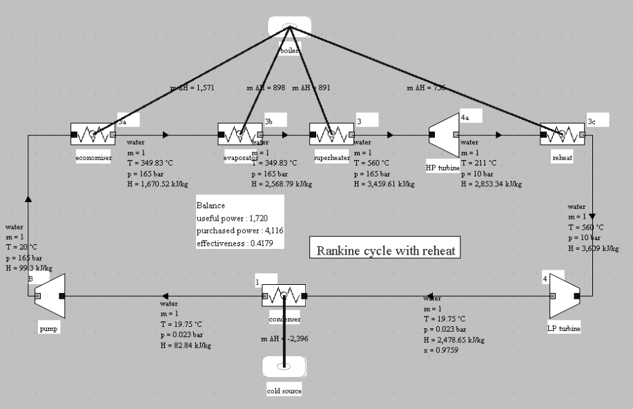
With the settings explained in the guided exploration and an intermediate pressure of 10 bar, the result of the reheat cycle modeling is provided by Thermoptim: the efficiency goes from 38% for the reference cycle to 41.8%. and the power output from 1174 kW to 1720 (Figure below).
Regenerative reheat steam power plants
The second area of improvement in power cycles consists in reducing irreversibility by temperature heterogeneity.
Let us examine the exchanges of the steam plant with its external sources in order to determine where the most important thermal irreversibilities are located.
On the cold source side, isothermal condensation limits the temperature difference between the working fluid and the coolant, so that irreversibilities due to temperature heterogeneity are low.
On the hot source side, on the other hand, a fuel capable of producing fumes at more than 2000 ° C is burned in the boiler to heat the working fluid to much lower temperatures: in the economizer the water comes out of the pump at a few tens of degrees Celsius, while vaporization and superheating take place at several hundred degrees C. In all cases the temperature differences with the hot source are very high, but it is clearly in the economizer that the greatest irreversibility by temperature heterogeneity is located.
Consider a cycle with reheat. If we extract a little quantity of steam, called bleed steam, at the outlet of the first expansion, at point 4a in the figure below, its pressure remains high enough to be able to condense it at a temperature allowing to preheat the pressurized water leaving the pump in point 2 in a mixer called an open feedwater heater.
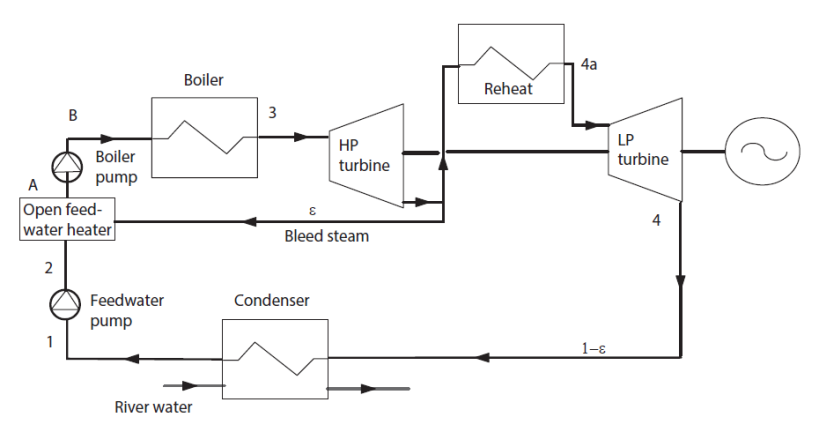
The enthalpy of the vapor being much greater than that of the liquid, due to the latent heat of vaporization, it is possible to preheat the liquid thanks to a small extraction of bleed steam during expansion.
This cycle is called regenerative Rankine cycle also known as extraction and reheat steam cycle.
Of course, for the operation to be possible, the bleed steam must be at a temperature higher than that of the liquid, which means that in practice, we must limit ourselves to a partial water preheating.
It should be noted that due to extraction, the mass flow rate of the fluid that evolves is not the same in the different parts of the machine. If ε is the bleed steam rate, the fluid flow between points 4a, 3c, 4, 1 and A is (1- ε) kg/s, and the flow-rate that evolves between points A, 3a, 3b, 3 and 4a is equal to 1.
The flow rate in the LP turbine being lower than in the reheat cycle, the capacity of the installation decreases slightly.
There are two kinds of feedwater heaters:
open feedwater heaters in which the hot fluid (the extracted steam) and the cold fluid (the condensed water) are mixed;
closed feedwater heaters in which the heat transfer between the two fluids takes place in a conventional heat exchanger. The condensed steam leaving the exchanger is then expanded to the condensing pressure and mixed with the steam leaving the LP turbine before entering the condenser.
In the first case, it is necessary to provide two pumps in the water circuit, while in the second, one is enough but you must install heat exchangers.
In practice, in high-capacity power plants used in electricity generation, several feedwater heaters of both kinds are used (from 6 to 9), operating at temperatures ranging from 30 to 50 °C.
Overall, extractions may contribute to an improvement of almost five points of the internal efficiency of the Rankine cycle. Combined with reheat, the gain is about 7 percentage points, a 20% higher efficiency than the basic cycle.
This cycle is the subject of guided exploration (C-M1-V5).
You will learn how to set a mixer and a divider.
Important note: to make this page easier for you to read, we have inserted here these guided explorations, but you should use the ones contained in the Thermoptim browser installed on your computer, because it is them that are coupled with Thermoptim and all the corresponding working files.
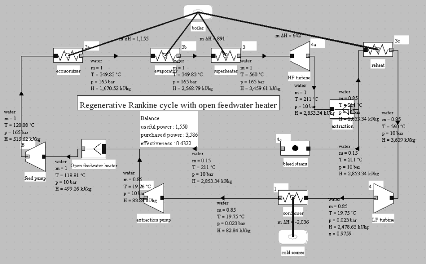
The synoptic view of a reheat and extraction cycle using an open feedwater heater modeled in Thermoptim is given in the figure below. We note the slight decrease in power: 1,550 kW instead of 1,727 kW of the reheat cycle, due to the reduction of the flow in the LP turbine.
The synoptic view of a reheat and extraction cycle using a closed feedwater heater modeled in Thermoptim is given in the figure below. Note that the efficiency is slightly lower than with an open feedwater heater, due to additional irreversibilities in the exchanger and the throttling of the condensed bleed steam.

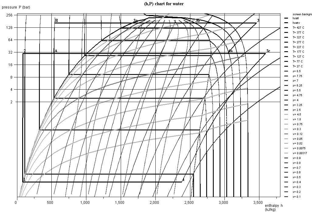
The figure below gives the plot of this cycle in the (h, ln (P)) chart, superimposed on the simple cycle, in dotted lines.
Design of a steam plant condenser
Reminders on the calculation of heat exchangers using the NTU method
The method of calculating the exchangers that we recommend is called the Number of Transfer Units or NTU method.
It is presented in this page of the portal, to which we suggest you refer if you do not remember it well.
You may also study this Diapason session.
Exploration Design of a steam plant condenser
This exercise is the subject of guided exploration STEAM-2
The objective of this exploration is to guide you through your first steps in setting up a steam plant condenser.
It follows on from the guided exploration S-M3-V7 which presented the cycle of a single pressure steam plant.
Important note: to make this page easier for you to read, we have inserted here these guided explorations, but you should use the ones contained in the Thermoptim browser installed on your computer, because it is them that are coupled with Thermoptim and all the corresponding working files.
PWR nuclear power plant cycles
In a Pressurized Water Reactor, for safety reasons, the maximum steam cycle temperature and pressure are limited at levels well below those used in flame plants. In current PWR plants, pressure in the generator is about 60 bar and the steam temperature rarely exceeds 275 °C.
A peculiarity of PWR nuclear power plant steam generators (SGs) is that there is no initial superheat. Complete expansion of steam from this state would lead to too low a steam quality, which would be both disadvantageous in terms of performance, and fatal to the mechanical strength of turbine blades. The solution adopted consists in using a special organ called the moisture separator reheater (MSR), to stage the expansion by providing a reheat at a pressure of about 11 bar, which can increase efficiency and meet the quality constraint at the end of expansion.
A moisture separator reheater receives steam partially expanded with a quality close to 0.87, the liquid phase of which is separated and directed to feedwater heaters, while the steam passes through a heat exchanger traversed internally by a small flow of saturated steam at high pressure (and therefore higher temperature), which condenses.
A PWR cycle is the subject of a guided exploration (C-M1-V8).
Exploration of a PWR cycle
A PWR cycle is the subject of a guided exploration (C-M1-V8).
In this guided exploration, you will learn how to set the moisture separator reheater and the PWR cycle.
This model is rather simple insofar as no extraction or reheat is taken into account, except for the moisture separator reheater.
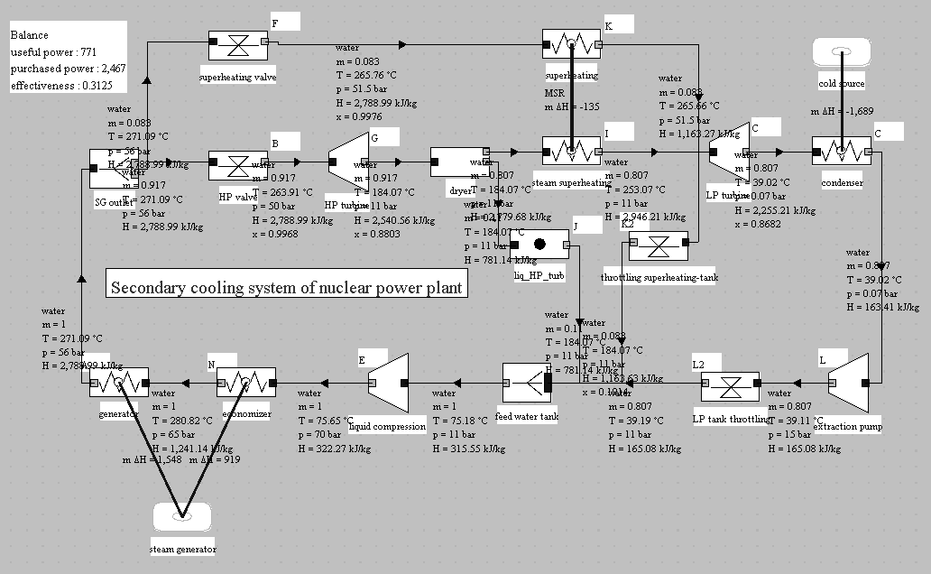
The figure below represents the diagram of a PWR cycle, modeled in Thermoptim, excluding feedwater heaters.