Introduction
 The block
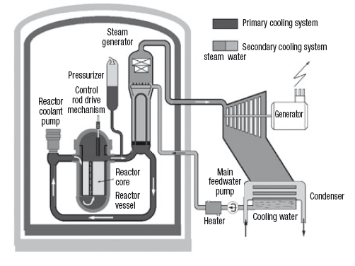
diagram of a PWR is given in this Figure. On the left side of the
diagram appears the containment structure comprising three main
organs:
The block
diagram of a PWR is given in this Figure. On the left side of the
diagram appears the containment structure comprising three main
organs:
- the reactor with its control system (control rod drive mechanism)
- the steam generator
- the pressurizer.
These three devices are connected by the primary circuit, including connecting pipes, and reactor coolant pumps, which circulate the coolant in the direction of the arrows.
The steam generator is connected to the secondary circuit located outside the containment structure, which corresponds to the thermodynamic cycle followed by steam, symbolized in the diagram by a turbine, condenser, feedwater pump and a heater.
For security reasons, water must be maintained at a pressure higher than the saturation pressure at its maximum temperature in the reactor core. The whole primary circuit needs to withstand this maximum pressure, which results in severe mechanical stresses.
In existing plants, the maximum temperature of the thermodynamic cycle is set at about 280 °C and the primary circuit at about 330 °C.
To ensure non-boiling primary water, the coolant system pressure is set at 155 bar, corresponding to a saturation temperature of 345 °C, which provides a small safety margin. Such pressure is already high and imposes severe technological constraints at all levels.
The steam generator (SG) is able to transfer the total power of the reactor to the secondary circuit, with a very low temperature difference, as the performance of the thermodynamic cycle increases as its temperature does.
Moisture separator reheater
Given the low temperature differences between primary and secondary circuits, the need to transfer significant power forbids in practice achieving any superheating in the SG, because the exchange coefficients between the primary liquid and superheated steam would be too small.
A peculiarity of PWR nuclear power plant SGs is, as we have seen, that there is no initial superheat.
Complete expansion of steam from this state would lead to too low a steam quality, which would be both disadvantageous in terms of performance, and fatal to the mechanical strength of turbine blades.
The solution adopted consists in using a special organ called the moisture separator reheater (MSR), to split the expansion by providing a reheat at a pressure of about 11 bar, which can increase efficiency and meet the quality constraint at the end of expansion.
 This
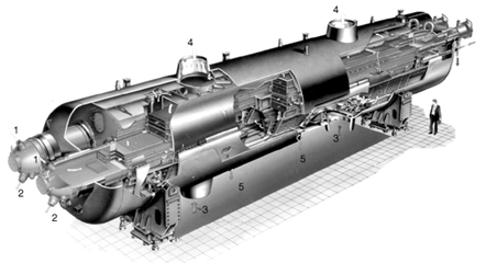
figure (Alstom Power Documentation) shows a moisture separator
reheater. Itreceives steam partially expanded with a quality close to
0.87, the liquid phase of which is separated and directed to feedwater
heaters, while the steam passes through a heat exchanger traversed
internally by a low flow of saturated steam at high pressure (and
therefore higher temperature), which condenses. On the cutaway of the
figure, live steam enters in 1 and leaves condensed in 2, while the
steam to be superheated enters in 3 and exits in 4, condensate
discharges being done in 5.
This
figure (Alstom Power Documentation) shows a moisture separator
reheater. Itreceives steam partially expanded with a quality close to
0.87, the liquid phase of which is separated and directed to feedwater
heaters, while the steam passes through a heat exchanger traversed
internally by a low flow of saturated steam at high pressure (and
therefore higher temperature), which condenses. On the cutaway of the
figure, live steam enters in 1 and leaves condensed in 2, while the
steam to be superheated enters in 3 and exits in 4, condensate
discharges being done in 5.
Loading the model
Loading the moisture separator reheater model
Click on the following link: Open a file in Thermoptim
You can also:
- either open the "Project files/Example catalog" (CtrlE) and select model m8.3 in Chapter 8 model list.
- or directly open the diagram file (MSR.dia) using the "File/Open" menu in the diagram editor menu, and the project file (MSR.prj) using the "Project files/ Load a project " menu of the simulator.
Modelling the moisture separator reheater
 To correctly model the separator - superheater in
Thermoptim, we need a phase separator, which is a particular node, and
a heat exchanger.
To correctly model the separator - superheater in
Thermoptim, we need a phase separator, which is a particular node, and
a heat exchanger.
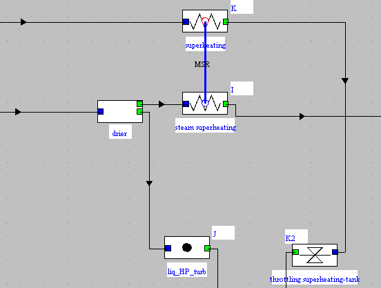
The moisture separator reheater has three components:
- the separator, which is a phase separator
- the "superheating" process, which represents the fraction of the flow of superheated steam leaving the steam generator at high pressure, which condenses
- the "steam superheating" process, which represents the medium pressure steam which is superheated.
The link between these two processes corresponds to the heat exchanger called MSR
Separator setting
Open the separator screen. It receives most of the flow, namely 91.7% of the total, leaving the HP turbine at medium pressure and at the corresponding saturation temperature, with a quality equal to 0.88.
We considered here that it is isobaric and that its efficiency is equal to 1 or 100%, which means that all the vapor is separated from the liquid.
The result of the calculation is that 11% of the total flow rate of the steam generator is found in the liquid state and is directed towards the feedwater tank, while 80.7% corresponds to saturated steam at medium pressure MP and is directed towards the superheater.
Reheater settings
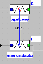 The reheater
is a heat exchanger. It is modeled in Thermoptim as a connection
between two "exchange" processes which represent one the hot fluid
(called here "superheating"), and the other the cold fluid (called
here "steam superheating").
The reheater
is a heat exchanger. It is modeled in Thermoptim as a connection
between two "exchange" processes which represent one the hot fluid
(called here "superheating"), and the other the cold fluid (called
here "steam superheating").
Open the "MSR" heat exchanger screen by double-clicking the blue link.
In the left part appear the characteristics of the hot fluid, which is the vapor coming from the condensing steam generator, and in the right part are displayed those of the cold fluid, leaving the separator, whose temperature goes from 184 °C to 253.4 °C, which corresponds to a superheating of approximately 69.6 °C.
To set the superheater, we set all the known elements, namely the flow rates of the two fluids, the state of the water entering and leaving the hot process (the high pressure steam which condenses), as well as the state of the water entering the cold process (the medium pressure steam that we are trying to superheat).
We have thus set five constraints, so that the exchanger can be calculated.
Downstream of the cycle
The superheated medium-pressure steam is directed to the low-pressure LP turbine, where it produces mechanical power, while the two other flows leaving the moisture separator reheater are mixed in the feed tank with the expanded and condensed HP steam, before to be compressed by the pump.
PWR pressurized water reactor cycle
Now that we have explained how the moisture separator reheater is modeled, we can open a simplified Thermoptim model of PWR cycle. This cycle is fairly close to a reheat and extraction cycle: due to the existence of three pressure levels, it requires two pumps.
For the reasons mentioned above, the steam generator does not include a superheater.
Loading the model
Loading a PWR cycle model.
Click on the following link: Open a file in Thermoptim
You can also:
- either open the "Project files/Example catalog" (CtrlE) and select model m8.4 in Chapter 8 model list.
- or directly open the diagram file (PWR.dia) using the "File/Open" menu in the diagram editor menu, and the project file (PWR.prj) using the "Project files/Load a project" menu of the simulator.
We find the model of the moisture separator reheater in the upper right part of the diagram.
The cycle efficiency is equal to 31.4%. Extractions that take place in reality can reach around 33.5%.
Cycle plot in the water (h, ln(P)) chart
First step: loading the water (h, ln(P)) chart
Click this button
You can also open the diagram using the "Interactive Charts" line in the "Special" menu of the simulator screen, which opens an interface that links the simulator and the diagram. Double-click in the field at the top left of this interface to choose the type of diagram desired (here "Vapors").
Once the diagram is open, choose "water" from the Substance menu, and select "(h, p)" from the "Chart" menu.
Second step: loading the PWR cycle
Click this button
You can also open this cycle in the following way: in the diagram window, choose "Load a cycle" from the Cycle menu, and select "cycle_PwrEnThin.txt" in the list of available cycles.
The two expansions are clearly shown in the diagram. The first (B-G) takes place entirely in the liquid-vapor equilibrium zone, while the second (I-C) begins in the vapor zone and ends in the liquid-vapor equilibrium zone.
The inlet point into the separator is G, and the two exit points H and J.
Interpreting the diagram is a bit tricky, since the flow rate varies depending on the process.
Cycle performance
Let us start by calculating the cycle balance
First law balance
What is the value of the useful power?
What is the value of the purchased power?
What is the value of the efficiency?
Influence of HP vapor flow rate in the superheater
As you can see, the power drops slightly, due to the reduction in the flow through the turbines, but the efficiency increases a little.
There is an optimum to be found between power and efficiency.
Parametric study of the PWR cycle
Exercise: study the influence of intermediate pressure on cycle performance.
Modify the intermediate pressure, studying its influence on cycle performance (efficiency and power).
To change the value of the intermediate pressure, change it in point G at the outlet of the HP turbine and click on "Calculate". Also modify it in point M at the inple of the second pump and click on "Calculate".
Calculate the HP turbine, and then recalculate several times in the simulator screen until the balance stabilizes.
Conclusion
This exploration allowed you to see how the constraint of non-superheating in the steam generator of a pressurized water nuclear power plant can be bypassed thanks to the moisture separator reheater.
Study by yourself the influence of the HP steam flow in the superheater on the balance of the cycle, increasing it slightly.
Start by opening the throttling process "superheating valve" at the outlet of the divider "SG outlet", enter "0.093" (kg/s) as flow value and recalculate the process.
Recalculate the divider "GV outlet".
Finally recalculate several times in the simulator screen until the balance stabilizes.