Introduction
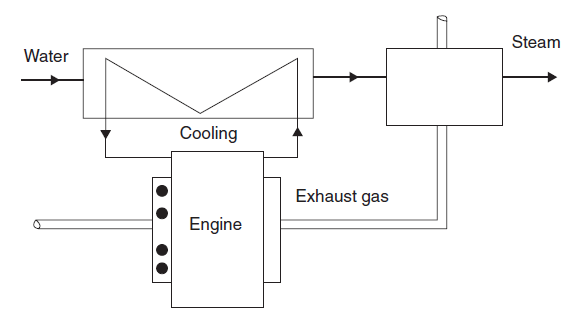
The Thermoptim model uses the one we presented during the study of alternative internal combustion engines, supplementing it with two cogeneration exchangers.
In this guided exploration, we will study a cogeneration installation using the industrial gas engine that we modeled with a Beau de Rochas cycle in another directed exploration (C-M2-V5b)..
Loading the cogeneration with industrial gas engine model
Loading the model
Click on the following link: Open a file in Thermoptim
You can also:
- either open the "Project files/Example catalog" (CtrlE) and select model m10.2 in Chapter 10 model list.
- or directly open the diagram file (gasMotorCogen.dia) using the "File/Open" menu in the diagram editor menu, and the project file (gasMotorCogen.prj) using the "Project files/Load a project" menu in the simulator.
The settings of this model require some explanation. For those on the engine alone, refer to the exploration on the gas engine (C-M2-V5b).
Configuration of the thermocoupler connected to the combustion chamber, representing the cooling of the engine by the cylinder walls
The coupling to the combustion chamber is carried out using a Thermoptim functionality that we have not yet introduced, that of thermocoupler.
A thermocoupler completes the heat exchangers by allowing components other than "exchange" processes to connect to one or more "exchange" processes to represent thermal couplings.
For a combustion chamber, the calculation is carried out to balance the thermal power transferred to the cooling fluid, itself defined by the combustion efficiency chosen.
In this example, its value is 0.79, which means that 21% of the power released by combustion is transferred via the thermocoupler.
Open the thermocoupler screen. It is analogous to that of an exchanger, the process exchange appearing on the left of the screen under the name of "thermal fluid", and the combustion chamber on the right, under the name of "process".
In this case, the user can only choose to calculate the outlet temperature of the exchange process at a given flow rate, and calculate the flow rate, this temperature being known.
In this example, we have chosen to determine the outlet temperature, the coolant flow rate being known.
The thermal power communicated to the water is 239 kW.
Settings of the exchanger on exhaust gases
The second exchanger is completely conventional. By choosing an effectiveness equal to 0.7, an additional power of 221 kW is recovered.
Calculation of the performance of the cogeneration system
Calculate the mechanical efficiency of the installation
Calculate the thermal efficiency of the installation
We call thermal efficiency the ratio of the heat transferred outside to the thermal power supplied to the cycle, that is to say here to the purchased power.
Calculate the overall efficiency of the installation
The ratio of the sum of the mechanical power and the heat produced to the thermal power supplied to the cycle is called overall efficiency.
Calculate the heat/force ratio of the installation
The ratio of heat produced to the mechanical power produced is called the heat/force ratio.
It is representative of the distribution of energy between heat and electricity
Application exercises
Calculate the new performance indicators of the cogeneration system for an engine compression ratio equal to 15 and a combustion chamber efficiency of 75% (0.75)
Modify the configuration of the compression and the expansion phase in a closed system by entering 15 instead of 12 for the compression and expansion ratios, then click on Calculate in each of these processes.
Change the combustion setting by entering 0.75 instead of 0.79 as the combustion chamber efficiency, then click Calculate.
Then recalculate several times in the simulator screen until the balance stabilizes.
Conclusion
This exploration allowed you to discover a model of a cogeneration installation with gas engine and to calculate its performance indicators.
Mechanical efficiency is the ratio of the mechanical power produced to the thermal power supplied to the cycle, that is to say here the useful power to the purchased power. It characterizes the performance of the facility as a generator of electricity.