Problems posed by technological design and off-design operation
Introduction
We have been led to distinguish two types of thermodynamic models:
• phenomenological models, implemented initially in Thermoptim, only give access to the calculation of thermodynamic cycles, irrespective of the choice of a particular component technology;
• technological design and off-design simulation models not only provide the same results as the previous ones, but in addition allow the user to geometrically design the various components and once the technological design is achieved, to study the behavior of the system outside the operating conditions for which it has been sized.
Such models are for example necessary when one wants to evaluate the performance of an existing facility, operated under conditions different from those for which it was designed. This audit issue (particularly with a view to proposing improvements) is of interest to a growing number of organizations, industrial and others.
This second class of models has so far been little studied, although it is the only means to really answer the questions asked by a lot of modelers. This somewhat paradoxical situation arises because such models are much harder to write and solve than those allowing one to calculate cycles, the latter being often already quite complex. Due to lack of appropriate tools, modelers have so far been forced to limit their ambitions in this area.
Let us make clear that what we call off-design analysis corresponds to the stabilized operation of a facility for operating conditions other than those for which it has been designed: it is not to study the fast transient behaviour caused by control actuators.
New features in Thermoptim versions 2.7 and 2.8 allow one to perform as well cycle studies as to simulate off-design operation of various systems, as we show in this section.
In this page, we make a brief presentation of how we can tackle this issue. Other pages of this portal provide more details (thematic pages on heat exchangers , displacement compressors , dynamic compressors , worked examples ), and we refer the interested reader to Part 5 of the first edition of the book Energy Systems and Volume 4 of Thermoptim reference manual .
Resolution principles for technological design and off-design operation
To perform technological design, we have introduced new screens in Thermoptim versions 2.7 and 2.8, complementary to those that perform phenomenological modeling.
These screens allow you to define the geometric characteristics representative of the different technologies used and the parameters necessary to calculate them. For a given component, they obviously depend on the type of technology selected.
For example, for an exchanger they define flow patterns and free flow area devoted to the fluid, hydraulic diameters, and for a piston compressor, isentropic or volumetric efficiencies.
Note that the estimation of these quantities is not always easy, because the manufacturers rarely provide them as such. They should generally be identified from the data sheets, charts or software made available to customers.
The most significant changes relate to heat exchangers, Thermoptim versions prior to 1.7 or 2.7 determining only the product UA of the overall heat exchange coefficient U by the area A of the exchanger, without the two terms being evaluated separately. To size a heat exchanger, that is to say calculate its surface, we must first choose a geometric configuration, and secondly compute U, which depends on the configuration, thermophysical properties of fluids, and operating conditions.
Compressors and turbines have also been equipped with technological screens that define the characteristics for determining the flow-rate and the isentropic efficiency from the compression ratio.
Computer implementation
The general principles of computer implementation are:
First, we must ensure consistency with Thermoptim "phenomenological" classes, which need to perform their calculations in the same way, the technology screens being present or not
Then, we have chosen to externalize as much as possible the computer implementation so that users can customize the calculations as much as they want. It is indeed almost impossible, on the one hand to find completely generic formulations given the multiplicity of technological options, and secondly to develop algorithms robust enough to solve the corresponding sets of equations
A generic driver allows you to some extent creating the technological screens and set them
Access to technological screens however generally requires the use of an external driver specific to the problem studied and programmed accordingly
Technological design and off-design classes being externalized, users can adapt them relatively easily to the particular problems they face. We therefore make available to them a work infrastructure significantly facilitating the task to ensure that the use of the software toolbox is as straightforward as possible.
A technological and simulation screen has been added to the simulator. (Figure below).
It has two main tables placed on its left side. The top one provides access to all the screens created by the technological driver. Buttons and displays in the right and bottom of the screen facilitate automatic recalculation, which can be triggered without returning to the simulator.
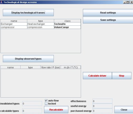
Technological and simulation screen
Off-design simulation
In this section, after recalling how Thermoptim calculates the components of a system, we introduce the specific off-design problems.
Another portal page presents various examples, including a fairly complex one which explains how the off-design operation of a refrigeration machine can be calculated.
Principle of computing coupled systems in Thermoptim
Calculate off-design operation of an energy technology consisting of several coupled components amounts to solving a system of equations which is usually highly non-linear.
Each component involving up to several tens of equations, it is common that a full project includes a few hundred. To solve them, it is possible to use powerful solvers, but this assumes that one can obtain an explicit formulation of these equations. In practical terms, the problem is then essentially to ensure the consistency of equations expressing the coupling between components. Without an appropriate environment, the task can be very complex and very difficult to secure.
Thermoptim has the advantage of facilitating the description of the technology studied thanks to its diagram editor, which ensures consistency of coupling between components. However, it does not in its current version formally express the equations that come into play: they are solved numerically by each component.
The Thermoptim simulator calculates step by step the various elements of a project. This is a sequential method of calculation, which differs from other modeling environments (matrix) in which all equations of the problem are solved simultaneously. This manner of proceeding has the advantage that it is much easier to calculate successively the elements one by one than solving the entire system at once.
However, it induces two problems:
first it may be necessary to iterate the calculations a number of times to find the right solution, especially if the system is coupled;
secondly, for a project a little complex, the question arises in what order calculations should be performed.
To solve this latter problem, a set of algorithms was developed. Called Thermoptim automatic recalculation engine, it is a key element of the package. A particular screen can be displayed if desired to follow recalculation steps, and thus ensure the relevance of modeling.
The automatic recalculation engine, however, is only able to calculate phenomenological models, in which the couplings between components are much simpler than when one wants to study the system in off-design mode. It was therefore necessary to supplement it with appropriate algorithms, the use of external drivers appearing to be the best solution.
System couplings between components
Many parameters, which were set exogenously in the phenomenological model, then depend on the initial design and adaptation of the machine to operating conditions.
By making these technology choices, we indirectly determine some parameters on which we could previously play freely. For example, in the case of a displacement compressor,the flow rate is not necessarily exactly the one that was desired: it depends on the swept volume, compression ratio, suction specific volume, volumetric efficiency, rotation speed etc.
To realistically simulate the system in off-design mode, we must be able not only to make the technological design of each component, but also to characterize the interactions between components due to their adaptation to new operating conditions.
For example, the condenser and desuperheater of a refrigeration machine do in fact form a single exchanger, whose total area is known. The adaptation of the exchanger to changes in its boundary conditions therefore requires a coupled calculation much more complex than that of the two separate parts.
Moreover, new systemic constraints appear: in the example above, the pressure levels are set by the thermal equilibrium of two phase-change heat exchangers, the evaporator and the condenser, which determine the saturation temperatures. As for the compressor, it sets the refrigerant volume flow (depending on its rotation speed and compression ratio that determine its volumetric efficiency), and therefore the mass-flow (depending on the specific volume of refrigerant at suction). The main parameters of the refrigeration machine, namely the pressure levels and flow-rate are determined by several strongly coupled components whose calculation cannot be done independently.
Numerical solving of coupling equations
The various off-design studies we have done have shown that there are two complementary difficulties:
The first is to carefully analyze the physical phenomena involved and to correctly model the behavior of the different components, which may be far from simple. We offer a number of models, including in this portal, but they are not the only ones possible, and we have not covered all the interesting cases;
The second is the numerical solving of the model coupling equations, which requires to find a suitable algorithm, and also to initialize it properly.
The solution we recommend is to use the minPack library as a solver initially developed in Fortran, and since then translated into Java. It is based on the Marquardt Levendberg method which combines the Gauss-Newton method and gradient descent. Its main interest is to be very robust and to only require as initialization an approximate solution.
Its implementation in Java is done using an interface called optimization.Lmdif_fcn, which forces the calling class (in this case our driver) to have a function called fcn().
This function fcn() receives as a main argument an array x[n] containing the variables and an array fvec[m] returning residues of the functions that we seek to set to zero.
The example of the refrigeration machine explains how you may operate in practice.
Remark
As mentioned above, the versions of Thermoptim that allow one to make technological design and off-design studies are versions 2.7 and 2.8.
