First Law of thermodynamics
Expressions for calculating the mechanical and thermal energy exchange of a fluid mass with its surroundings have been established in another page.
We will now present the First Law of thermodynamics. As usual, we start with the expression for closed systems, well known to all, and we generalize for open systems.
The First Law, also known as the equivalence principle or the energy conservation principle, says that the energy contained in an isolated system or evolving in a closed cycle, remains constant, whatever the processes it undergoes. The various forms that can take the energy of a system: mechanical energy, heat energy, potential energy, kinetic energy etc. are all equivalent to each other under the First Law.
Definition of internal energy U (closed system)
Any closed physical system is characterized by a scalar U, based exclusively on state variables, and such that for any real process:
K being the kinetic energy of the system, W the work of external forces, expressed for the total mass of the system and given by relation: W = WA + Wv, and Q the heat exchanged by the system with outside for the process considered.
U is an extensive quantity called the internal energy of the system, U + K is sometimes called the system total energy. For a phase of mass m, U = m u, u being the specific internal energy.
Let us recall that the state variables that define, in the most general case, a physical system, fall into four broad categories:
mechanical variables, position or deformation;
temperature;
chemical variables;
electric variables.
Only the first two will be considered in most applications we have to deal with, and the third will be used for fluid mixtures and combustion reactions. As for the fourth, it will not intervene in the context of this portal.
Note that many authors distinguish in the expression of the First Law the work of gravity (Wv ) and pressure forces (WA), and therefore express it under the equivalent form:
ΔU + ΔK + mg Δz = WA + Q
For an infinitely small control volume, Equation (1) becomes:
dU + dK = dW + δQ (2)
Physically, the First Law derives from the experimental evidence that, whatever the processes undergone by a given system, the sum W + Q depends only on the initial state and final state. It follows therefore that W + Q is a state function of the system.
Mathematically, the First Law states that, while δW and δQ are not exact differentials, their sum is one, and is equal to the sum of kinetic energy changes and a function state, the internal energy.
Application to a fluid mass
In the case of a single fluid phase, the physical state of the system, expressed in mass quantities, is characterized by variables P, v, T, connected by the equation of state. u is a function of these variables, or more precisely two of them.
Let us apply the First Law to a fluid infinitesimal reversible process, neglecting the action of gravity. During this process, the kinetic energy remains constant equal to zero, which implies dK = 0.Moreover δW = - Pdv and δQ is expressed as:
δQ = du + Pdv (3)
By identification with the calorimetric equation, we get :
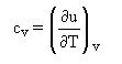
which is often used as a definition of cv.
The previous equation shows that for a constant volume heating without mechanical friction, the heat exchanged with the outside is equal to the change in the fluid internal energy.
Q= u2 - u1
This relationship is the basis for calorimetric determinations of u
Work provided, shaft work
Industrial operations generally take place continuously, each component (turbine, pump, valve etc.) permanently receiving and evacuating matter. When, as it is often the case, their operating conditions are stabilized, possibly periodically, it is called "permanent" or "steady-state". As mentioned previously, the calculation of these devices must be done in an open system, and the previous expression, valid only in a closed system, must be generalized.
The reasoning principle is to follow the evolution of a closed control volume, and calculate the work of external forces on all its boundaries, distinguishing between cross sections of the fluid, fixed walls, which obviously neither produce nor receive work, and moving walls like blades, in which some work
 is exerted, called "
shaft work".
is exerted, called "
shaft work".
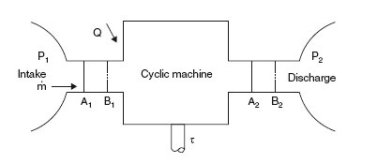
Periodic machine
In the most frequent case (Figure above) we can assume that the component operates between two chambers of large dimensions, where the fluid is in equilibrium. The upstream (1) and downstream (2) states are defined by their pressure and temperature, assumed to be uniform despite the extractions and contributions due to the suction and discharge. For example, a gas turbine compressor sucks in air and discharges into the combustion chamber where the pressure is substantially uniform.
In its passage from (1) to (2), each unit mass of fluid receives from the moving walls the shaft work
, whose knowledge is fundamental, since its product by the mass flow-rate gives the power involved (neglecting mechanical losses in bearings and transmission).
One can easily show that, per unit mass, a component performing any kind of processing provides work
algebraically equal to the work of pressure forces calculated in a closed system WA, increased by the transfer work, that is to say the variation of product Pv:
= WA + P2v2 - P1v1 = WA + Δ(Pv)
Note that in the previous demonstration, we made no assumption on the restrictive nature of the processes in the machine itself. We simply recognized that the pressure was uniform and constant in the course of time at the inlet and outlet of the machine. The relationship obtained thus applies only in this condition, whatever the intermediate processes, whether reversible or not.
Special case of a reversible process
If the process is reversible,

We recognize the expression of integration by parts, hence:
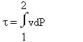
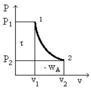
All of these relationships can be represented graphically in the Clapeyron diagram, which corresponds to the plane (v, P), v x-axis, P y-axis (Figure above). The area between the curve 1- 2 showing the process and the x-axis is equal to the opposite of the work of external forces WA, while the area between the curve and the y-axis is equal to shaft work
.
Note that these surfaces depend on the route of the curve 1 - 2, and therefore that mere knowledge of the initial and final states is not sufficient to determine WA and
.
Mathematically, this follows from the important fact that the differential expressions -Pdv and vdP are not exact differentials. Physically, it is explained by the intervention of one form of energy other than mechanical work, i.e. thermal energy.
If two different reversible processes starting from the same initial state 1 and ending at the same final state 2 do not correspond to the same shaft work, this is because the fluid does not exchange the same amount of heat with the outside during these two processes
It is for this reason that we note the differential forms with a small δ (δWA, δ
) and exact differentials by d.
Let us come back to equation (1) and express it according to t instead of W, for the total mass of the system. It comes:
ΔU + ΔK = W + Q = WA + Wv + Q =
- Δ(PV) - mgΔz + Q
which can be written:
Δ(U + PV) + ΔK + mg Δz =
 + Q
+ Q
Let us call enthalpy the state function H = U + PV and specific enthalpy function h = u + Pv.
The enthalpic form of the First Law is therefore written in mass variables (note that K,
and Q are now expressed in mass quantities):
Δh + ΔK + gΔz =
+ Q (6)
For an infinitely small control volume, this equation becomes:
dh + dK + gdz = δ
+ δQ (7)
Transposing the preceding reasoning, we find that the calorimetric equation writes as:
δQ = dh - vdP (8)
and:
which is often used as a definition of cp.
This notion of shaft work is far from trivial. In practical terms however, it poses no particular problem; in all the compression and expansions in open systems, the useful shaft that must be considered in the calculations.
