New and renewable energy cycles
Introduction
We study here three technologies for the thermodynamic conversion of renewable energies, namely direct solar energy cycles, those intended to valorize the thermal energy of the seas, and finally geothermal installations.
Technological explanations are given in these pages :
Solar powered cycles
A presentation of the various types of solar collectors is given in this page.
Low temperature flat plate solar collector model
Flat plate solar collectors differ depending on the type of coverage: unglazed (swimming pools), single or double glazing, vacuum, anti-emissivity coatings. Their transmittivity
 depends on this coverage. Because the effectiveness of solar collectors drops with temperature, it is preferable to operate at temperatures as low as possible given the intended use.
The solar flux received by the collector goes generally through a glazing intended to isolate the absorbing surface. Reflection, transmission through the glazing and absorption result in optical losses, characterized by an overall transmittivity
.
The absorber heats up and loses heat to the outside essentially by radiation and convection. This heat exchange can be characterized by a thermal loss coefficient U. A thermal fluid cools the absorber, taking useful heat that is then transferred or converted for different uses.
Based on this brief analysis, it is possible to produce a model whose parameters are:
• glazing transmittivity
;
• thermal loss coefficient U (W/m2/K);
• incident solar flux G (W/m2) ;
• collector surface A (m2) ;
• outside temperature Tout (°C).
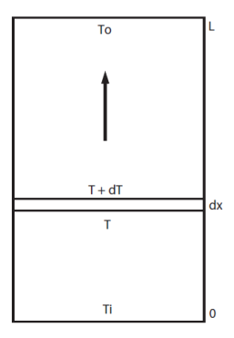
The heat balance of a small slice of collector length dx is: the power carried out by the fluid
 is equal to the radiation received reduced by optical losses
 , less the collector heat loss
 .
.
This is a differential equation that integrates seamlessly and leads to:

This equation is valid whatever the value of the flow. However, it can be replaced by a simplified formula when the flow is high enough that it can be assumed that the temperature varies almost linearly between the inlet and outlet of the collector. We write then that the losses are proportional to the average temperature Tm, itself equal to half the sum of inlet and outlet temperatures :

These are the models proposed in Thermoptim model library.
Two calculation methods are possible: to determine the outlet point state knowing the collector surface, or determine this surface knowing the outlet point state.
The model input data are as follows (provided by other system components):
• the thermal fluid temperature at the collector inlet Ti (°C);
• the flow of the thermal fluid (kg/s).
The outputs are:
• the thermal fluid temperature at the collector outlet To (°C);
• the thermal power received by the thermal fluid Q (W/m2);
• the collector effectiveness.
High temperature solar collectors
The low temperature flat plate collectors we just presented do not allow electricity to be produced with acceptable efficiencies. It is desirable to approach or exceed 100 °C to consider thermodynamic conversion of solar energy.
It is therefore possible to use flat plate solar collectors provided that their absorber is very well thermally insulated, which implies both an anti-emissivity treatment and good convective insulation.
Vacuum tube collectors are now seriously considered a solution for that. These collectors are usually made up of modules comprising a U-shaped pin of small diameter (of the order of 1 cm) provided with fins and inserted into a glass tube of large diameter (about 1 dm). The coolant circulates inside the pin. Such modules are placed to form parallel flat plate collectors (Figure below).

The solar collector model presented above is based on two assumptions that we will refine in this section:
• first, we assumed that losses are proportional to the temperature difference between the thermal fluid and the surroundings;
• second the absorber section is assumed to be equal to that of the collector.
The new model is a variation of the above, adapted to represent high temperature concentration collectors.
The solar flux received by the collector is first reflected on the concentrator mirrors and goes then through the glazing material thermally insulating the receiver where it is absorbed by a suitable surface. In high concentration collectors, only the direct component of solar radiation can be directed to the receiver, as the diffuse component cannot be concentrated.
The loss coefficient U can often be decomposed into a constant term and a term proportional to the temperature difference between absorber and ambient air: U = U0 + U1 (Tm - Tout).
is a function of radiation angle of incidence, mirror reflectivity, absorber absorptivity and transmittance of the glazing protecting the absorber.
With the previous notations, and assuming a linear distribution of temperatures in the collector (the assumption is only valid if the flow is not too small, which is often the case in practice) the model equation is as follows, Tm being the average absorber temperature, and Sc and Sa being respectively the collector and absorber surfaces:
Q = m Cp (To - Ti) =
Es Sc - Sa (U0 + U1 (Tm - Tout)) (Tm - Tout)
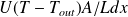
The figure below compares the effectiveness of different solar collectors, depending on the temperature difference between the absorber and the surroundings for an irradiation of 1,000 W/m2. It illustrates the value of concentration, but also shows that vacuum tube collectors, which do not require device tracking, remain attractive to just above 100 °C.
Example of a solar power generator
We limit ourselves to an example of a gas micro-turbine coupled to a parabolic dish.
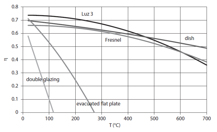
Micro-turbine solar concentrator (exploration C-M4-V1)
This exploration presents the cycle of a parabolic solar concentrator with regenerative gas micro-turbine: the hot air solar receiver is placed upstream of the combustion chamber of a regenerative gas micro-turbine, thus reducing consumption of fuel.
Important note: to make this page easier for you to read, we have inserted here these guided explorations, but you should use the ones contained in the Thermoptim browser installed on your computer, because it is them that are coupled with Thermoptim and all the corresponding working files.
The figure below shows a micro-turbine solar concentrator cycle: the solar hot-air receiver is located upstream of the combustion chamber of a micro-turbine, thereby reducing fuel consumption, and leading to correct efficiency (31% by taking into account the solar heat in the purchased energy).
OTEC cycles
OTEC means Ocean Thermal Energy Conversion. OTEC cycles are designed to generate electricity in warm tropical waters using the temperature difference between water at the surface (26-28 °C) and in depth (4-6 °C), from 1000 m.
In all cases, the need to convey very high water flow rates and pump cold water at great depth induces significant auxiliary consumption. Optimization of an OTEC cycle is imperative to take into account those values.
Two main types of cycles are used: closed cycles and open cycles. We will give an example of the first ones here.
Closed cycles use hot water at about 27 °C to evaporate a liquid that boils at a very low temperature, such as ammonia or an organic fluid. The vapor produced drives a turbine, then is condensed by heat exchange with cold water at about 4 °C from deeper layers of the ocean
The thermodynamic cycle is similar to that of a steam cycle, except for the working fluid (Figure below). The design of heat exchangers is of course even more critical given the very small temperature difference between hot and cold sources. Pinch values should be as low as possible while remaining realistic.

A possible Thermoptim model of this cycle is the subject of guided exploration (C-M1-V9).
Its synoptic view is given in the figure below. Its efficiency is 2.84%.
The hot water flow-rate is here equal to 27,000 kg/s, its temperature 26 °C and the cold water temperature 4 °C.
Let us calculate for this cycle the value of the Carnot effectiveness, with Tc = 4 + 273.15 = 277.15 K and Th = 26 + 273.15 = 299.15 K: eta = 7.35%. The actual efficiency is therefore equal to around 39% of the theoretical one, which is not that bad.

Geothermal cycles
Geothermal energy comes from the gradual temperature increase as one penetrates deeper into the earth's crust, either because of the natural gradient (3 °C/100 m, with an average flux of 60 mW/m2), or because of geophysical singularities (high temperature natural geothermal reservoirs of porous rock).
It is customary to distinguish three broad categories of reservoirs, according to their temperature levels:
high temperature (> 220 °C);
intermediate temperature (100 – 200 °C);
low temperature (50 – 100 °C).
In the first case, the geothermal fluid can be essentially composed of water or steam, in the other two it is water, optionally under pressure. A special feature of geothermal fluid is that it is never pure water: it also includes many impurities, corrosive salts (the concentration limit for an operation to be possible is equal to 1.5 mol/kg) and non-condensable gas (NCG) in varying amounts (0.1-10%). We shall see that this feature imposes constraints on thermodynamic cycles that can be used.
For environmental reasons, the geothermal fluid should generally be reinjected into the reservoir after use, but it is not always the case.
Single-flash geothermal power plant
We will just give an example of a single-flash geothermal power plant
Generally, the well contains a low quality (below 0.5) liquid-vapor mixture, which cannot be sent directly to the turbine.
If the initial pressure is sufficient, a solution is to partially expand the mixture in order to vaporize a portion, which is then sent to the turbine, while the liquid fraction is reinjected (Figure below).

The vapor phase typically contains a significant amount of non condensing gases NCG to be extracted if we want to condense water at the turbine outlet.
Note that steam through the turbine is condensed as distilled water which can sometimes be valorized notably as drinking water.
Such a cycle is the subject of guided exploration (C-M4-V3).
The figure below shows the synoptic view of such a cycle modeled in Thermoptim. We assumed that we had 760 kg/s of hot water in the saturated liquid state at 230 °C and 28 bar.
This water undergoes a flash at 6 bar, leading to a 0.15 quality. The liquid and vapor phases are then separated, the first being recompressed before reinjection, whereas the latter is expanded at the pressure of 0.123 bar (50 °C) and then condensed. The mechanical power produced is 57 MW and efficiency 9.6%.
Note that the pressure at which the flash is performed (6 bar) has not been optimized. The condensing pressure and temperature are relatively high because of noncondensable gases present in the geothermal fluid.

