Introduction
We will study the model of a single flash geothermal power plant.
Generally, only a low quality liquid-vapor mixture (less than 0.5) is available at a geothermal well.
If the initial fluid pressure is sufficient, it is possible to partially expand this mixture isenthalpically in order to vaporize part of it, which is then turbinated, while the liquid fraction is reinjected.
This operation is called performing a flash.
The vapor phase generally contains a significant quantity of non-condensable gases NCG which must be extracted if the water leaving the turbine is to be condensed. We use for this an ejector that we will not represent in our model.
It should be noted that the steam passing through the turbine is distilled water which can sometimes be used in particular as drinking water.
Loading the single flash geothermal power plant model
Let us study the single flash geothermal power plant cycle.
Loading the model
Click on the following link: Open a file in ThermoptimOpen a file in Thermoptim
You can also:
- either open the "Project files/Example catalog" (CtrlE) and select model m8.7 in Chapter 8 model list.
- or directly open the diagram file (Geoth1Flash_En.dia) using the "File/Open" menu in the diagram editor menu, and the project file (Geoth1Flash_En.prj) using the "Project files/Load a project" menu in the simulator.
The setting of this model requires some explanation.
Model setting
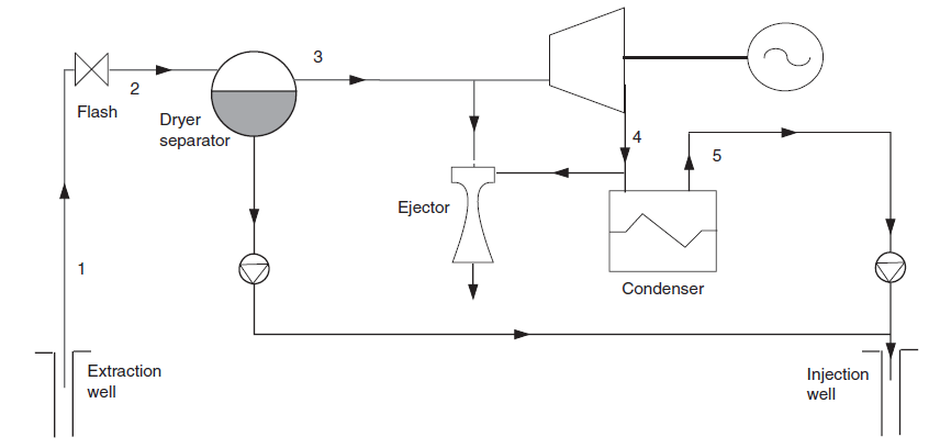
It has been assumed in this model that the geothermal fluid is in the form of water in the liquid state, at a pressure of 28 bar and at the saturation temperature at this pressure (230 °C).
The flash is an isenthalpic expansion without work. It is therefore modeled by a simple throttling process. The water undergoes a flash at 6 bar, which leads to a quality of 0.15.
The two-phase mixture emerging from the flash is then separated, the liquid phase being reinjected into the well after being recompressed.
The vapor phase is expanded in a condensing turbine at a pressure of 0.123 bar (50 °C).
As indicated above, the condensed water can then be used for various uses, in particular for drinking.
The mechanical power produced is worth 57 MW.
In a geothermal cycle, the calculation of the purchased energy is not always immediate, since the geothermal fluid (which is assimilated to water) is most often distributed in several flows, reinjected or not. We can therefore only rarely estimate the enthalpy it gives up.
In our Thermoptim model, this is why we have not introduced a process representing purchased energy, so that the balance sheet values are incomplete.
However, to be able to estimate an efficiency, we can consider as a reference a cycle which would make it possible to reinject all of the geothermal fluid at a temperature equal to 50 °C.
On this basis, a simple calculation leads to a efficiency equal to 9.6%.
Cycle plot in the (h, ln (P)) chart
First step: loading the R134a (h, ln (P)) chart
Click this button
You can also open the diagram using the "Interactive Diagrams" line in the "Special" menu of the simulator screen, which opens an interface that links the simulator and the diagram. Double-click in the field at the top left of this interface to choose the type of diagram desired (here "Vapors")..
Once the diagram is open, choose "water" from the substance menu, and select "(h, p)" from the "Chart" menu.
Second step: loading the geothermal cycle
Click this button
- in the diagram window, choose "Load a cycle" from the Cycle menu
- and select "geoth1flash.txt" from the list of available cycles.
- Then click on the "Connected points" line in the Cycle menu.
You get the cycle plot in the (h, ln (P))chart .
The flash from the "hot water inlet" point on the liquid saturation curve at 26 bar is represented by the small vertical segment. The separation of the two phases at 6 bar corresponds to the two horizontal segments to the left and to the right of the "flash" point.
The expansion in the turbine and the condensation of the turbinated water are also clearly visible.
Although it is not closed, we speak of cycle, by abuse of language.
Application exercise
You can now perform sensitivity analyzes of the performance of this cycle to its various parameters, such as the intermediate pressure at which the flash is produced.
Conclusion
This exploration allowed you to discover a model of a single flash geothermal power plant and the specific settings it uses.
Double flash geothermal power plant
If the pressure at the well outlet is sufficient, it is possible to perform a double flash, which makes it possible to recover steam at two different pressure levels and to increase the performance of the plant.
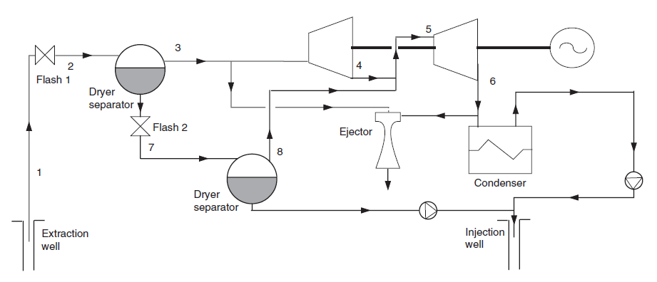
As this diagram shows, the liquid flow which, in the previous cycle was recompressed then reinjected, this time undergoes a second flash at the pressure of 0.931 bar, which leads to a quality of 0.115.
The liquid phase is recompressed and reinjected, while the vapor phase is mixed with the vapor flow from the first flash.
The whole is then expanded in a LP turbine at the condensing pressure.
The mechanical power produced goes from 57 to 77 MW, which represents an increase of 35%. The efficiency can be estimated at 13%.
If you are interested in this model, you can load it by opening the diagram file (Geoth2Flash_En.dia) using the "File/Open" menu in the diagram editor menu, and the project file (Geoth2Flash_En.prj) using "Project files/Load project" menu in the simulator screen.