Components and functions
Notions of working fluid and cycle
In this section, we will show that energy technologies only involve a very small number of functions. We will establish this by analyzing the components of three different technologies, the steam power plant, the gas turbine and the refrigeration machine. However, we will begin by defining two concepts essential for the whole book, that of working fluid and that of cycle.
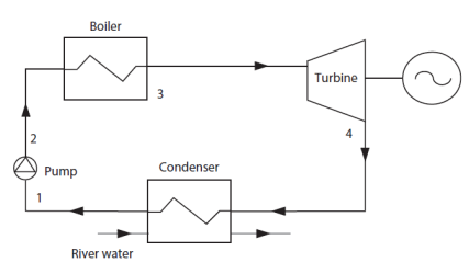
A steam power plant is essentially comprised of the following components:
a boiler where the fuel (solid, liquid or gas) is burned for generating steam (usually superheated)
a steam turbine in which this steam is then expanded. The turbine shaft provides the power output (figure below).
a condenser in which the steam leaving the turbine is completely liquefied (water)
a pump which restores the boiler pressure.
In a gas turbine (Figure below), air is drawn in on the left side of the machine by a compressor. A fuel burns with this compressed air in the combustion chamber, bringing the gases to high temperature.
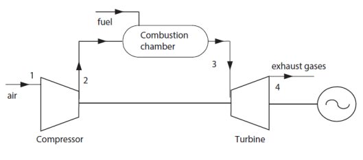
These hot gases are expanded in a turbine which is used first to drive the compressor, and second to drive the alternator or an engine shaft. The gases are then released into the atmosphere on the right of the machine.
As in these two examples, all the thermal machines which convert heat into work or the reverse are traversed by at least one fluid which undergoes various processes or processes, such as heating, cooling, compression or expansion, and which exchanges energy with the surroundings.
In a steam plant, it is water, in a gas turbine air and flue gas. As we will see later, in a refrigerator it is a refrigerant.
Generally, this fluid is called thermodynamic fluid or working fluid.
In the steam plant, the working fluid passes successively through each of the components, to return to its starting state.
In many energy systems, as in this example, the fluid undergoes a series of processes which lead it to return to its initial state.
We then speak of a cycle. This is another fundamental notion that we will often use.
In the case of a gas turbine, as in all internal combustion engines, the exhaust gases are released into the atmosphere, so it is improper to speak of a cycle.
However, by extension, we come to speak of a cycle to qualify the representation of the succession of thermodynamic changes undergone by the fluids used in an energy technology.
Steam power plant
The steam plant cycle, known as Rankine cycle or Hirn cycle, converts high temperature heat into work on the turbine shaft. We are talking about a power cycle.
Steam power plant cycle
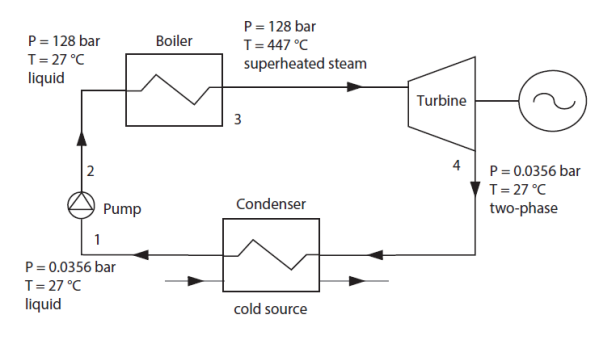
The setting values we give here (Figure 2.8) have been chosen so that the cycle will be easily plotted in the thermodynamic (h, P) chart, as we will see later.
At point 1, the water enters the pump in the liquid state and at very low pressure (about 1/30 bar).
It is compressed there and leaves it at point 2 at a pressure close to 128 bar, still in the liquid state.
In the boiler, a fuel (solid, liquid or gaseous) is burned, thus generating hot gases which are cooled by the working fluid, namely water.
By staying at about the same pressure, the water goes from the liquid state at point 2 to that of superheated steam at point 3, where it is brought to the temperature of 447 °C.
The superheated steam at point 3 is then expanded in a steam turbine, which allows mechanical power to be produced on its shaft.
It leaves at point 4 at the low pressure of the cycle, its temperature again becoming equal to 27 °C. Its state corresponds to a mixture of liquid and vapor, called two-phase state.
The steam exiting the turbine at point 4 is then completely liquefied at point 1 by cooling in the condenser. The pump then restores the water to the boiler pressure at point 2.
Note that the condenser is cooled by an external cold source, usually outside air or water from a river or sea.
The working fluid circuit has two parts at different pressures, the high pressure HP at 128 bar in the boiler, and the low pressure LP at 0.0356 bar in the condenser.
This is a characteristic common to most the cycles that we will study: they implement at least two pressure levels, the pumps and compressors passing the working fluid from the low pressure LP to the high pressure HP, and the turbines and valves from the HP to the LP.
Functional analysis
The steam plant cycle can thus be broken down into three functions: compression, heat exchange and expansion.
the working fluid is compressed in the pump
it exchanges heat in the boiler to bring it at high temperature
the working fluid is then expanded in the turbine
it exchanges heat in the condenser to cool it to the initial state
In all power cycles, we find these three functions, succeeding each other in this order: the working fluid is compressed, then heated and finally expanded.
Gas turbines
Today, gas turbines are experiencing a very strong development in many applications: air transport, power generation, cogeneration, driving machines (compressors and pumps). Among the arguments in their favor are their small size, excellent power to weight ratio, their quick start, good performance and low emissions of pollutants.
Technological aspects
There are two main categories of gas turbines: industrial gas turbines, heavy and robust, but of average performance, and gas turbines "derived from aviation" or "aeroderivative", much lighter and efficient, but also more expensive.
We speak of aeroderivative machines because these are variants of turbojets. To obtain high performance, their architecture can involve several sets of compressors and turbines rotating at different speeds.
The turbines are also generally axial.
The main technological constraints are at the level of the first stages of the expansion turbine, which are subjected to the flow of exhaust gases at very high temperatures.
Gas turbine cycle
At point 1 (Figure 2.12), the air enters the compressor at atmospheric pressure (about 1 bar).
It is compressed there and leaves it at point 2 at 434 °C and 16 bar.

In the combustion chamber, the working fluid is brought to the temperature of 1065 °C, always at the pressure of 16 bar. Given combustion, its composition varies: from air at point 2, it becomes burnt gases at point 3.
In the turbine, the working fluid is expanded to the pressure of 1 bar at point 4. Its temperature drops to 495 °C.
The gases are then released into the atmosphere.
As with the steam power plant, this cycle, known as Brayton cycle, operates between two pressure levels: the LP at the intake and at the exhaust, and the HP in the combustion chamber, the compressor and the turbine passing the working fluid from one level to another.
Functional analysis
The gas turbine cycle can thus be broken down into the three successive functions that we identified earlier.
compress the working fluid
heat it to high temperature
expand the working fluid
As we indicated during the presentation of steam power plants, we find these three functions in all power cycles, successive in this order: we compress, we heat and we expand.
Refrigeration machine
Principle of operation
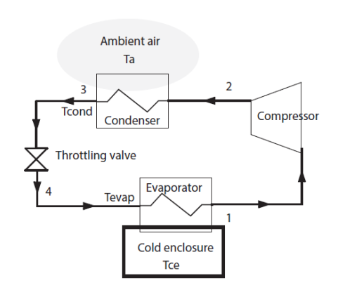
In a vapor compression refrigeration installation, an attempt is made to maintain a cold enclosure at a temperature below ambient.
To achieve this, a low pressure (and therefore low temperature) refrigerant is evaporated in an exchanger placed in the cold enclosure. For this, the temperature Tevap of the refrigerant must be lower than that of the cold chamber Tce.
The fluid is then compressed to a pressure such that its condensation temperature Tcond is higher than the ambient temperature Ta. It is thus possible to cool the fluid by heat exchange with the ambient air or with a cooling fluid, until it becomes liquid. The liquid is expanded at low pressure in a valve, without production of work, and directed into the evaporator. The cycle is thus closed.
This figure shows that a refrigeration machine is comprised of four components:
an evaporator
a compressor
a condenser
a throttling valve
This cycle converts the work on the compressor shaft into production of cold at low temperature. We are talking about a cycle working in reverse or refrigeration cycle.
As for the steam power plant, we speak here rightly of a cycle because, successively traversing the four components of the machine, the working fluid undergoes a series of processes which lead it to return to its initial state.
Refrigeration machine cycle
Let us study how a refrigeration cycle works and what values can take its parameters (Figure below).
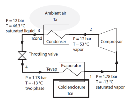
At point 1, a refrigerant, R134a, enters the compressor in the saturated vapor state: pressure of 1.78 bar and temperature T = - 13 °C.
It is compressed there and leaves it at point 2 at a pressure of 12 bar and at 53 °C, in the vapor state.
The pressure of 1.78 bar was chosen so that the vaporization temperature of R134a at this pressure is lower than that of the cold enclosure which is - 8 °C.
The pressure of 12 bar was chosen so that the vaporization temperature of R134a at this pressure is higher than that of ambient air which is 35 °C.
The cooling of the fluid in the condenser by exchange with the outside air comprises two stages: desuperheating in the vapor zone followed by condensation to point 3 in the saturated liquid state at 12 bar and 46.3 °C.
The working fluid is then expanded without producing work to point 4 in the two-phase state at 1.78 bar and -13 °C, before being directed to the evaporator.
As with the steam power plant and the gas turbine, the cycle operates between two pressure levels: the LP at the evaporator, and the HP at the condenser, the compressor and the throttling valve passing the working fluid from one level to the other.
Functional analysis
This first overview of the operation of a refrigeration machine allowed us to see that this cycle calls upon two of the component types already encountered in the previous cycles:
a compressor
heat exchangers
It also makes use of a component of a new type: the throttling valve.
Note that the refrigeration machine cycle can be broken down into three functions:
compress the working fluid
exchange heat to cool it at high pressure
expand the working fluid without producing work
exchange heat to bring it to the initial state
In all the refrigeration cycles, we find these three functions, succeeding each other in this order: we compress, we cool and we expand. Note that in some refrigeration cycles, expansion may take place in a turbine instead of a valve, with work production, but this is generally not the case.
Four basic functions
We have just seen that even if the technical solutions implemented are varied, working fluids are subjected to only four different types of processes:
compression;
expansion with work production;
expansion without work production;
temperature change (heating and cooling).
Therefore four functions are sufficient to describe the operation of these machines:
compression can occur with the fluid being liquid or gaseous. In the first case the component is a pump, in the second a compressor;
expansion with work production is generally made through turbines;
expansion without work production occurs in valves;
heating can be generated either in combustion chambers or boilers, or in heat exchangers. Cooling is usually done in heat exchangers.
This finding has a very broad bearing: in all engines, the working fluid is successively compressed, heated, expanded and cooled or released to the atmosphere, and, in all refrigeration cycles, it is compressed, cooled, expanded, and heated or released to the atmosphere.
The different components of thermal machines can thus be grouped into a small number of functional categories. Furthermore, they can in certain conditions be calculated independently of each other when we know the corresponding thermodynamic changes.
The diagram in Figure below summarizes the links between the components of the systems we have studied and these four functionalities.
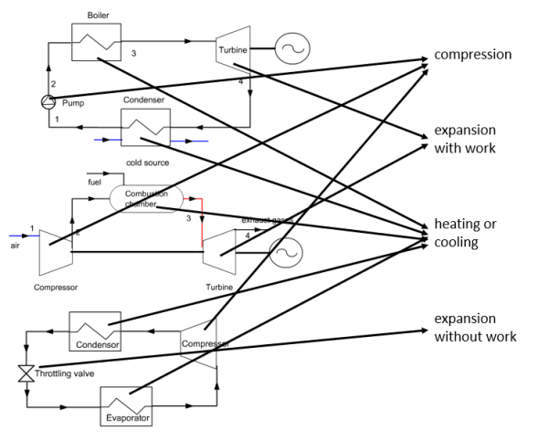
From these functions it is possible to represent a large number of energy technologies, from the simplest like those we have studied here, to large systems.
Self assesment activities
We have introduced the cycles of the three simplest and most popular energy technologies.
It is important that you understand their architecture, how they work and know the names of their components.
These self-assessment activities will allow you to test your knowledge on these topics:
The following self-assessment activities will allow you to check your understanding of these concepts:
