Productive structures and exergy balances
Productive and dissipative units
Each component of the physical schema is related to a productive or dissipative unit (PDU).
Each PDU allows one to calculate the exergy balance of a componen: each unit gets "fuels" Fi which can be of three types (heat-exergy or chemical exergy, work, or exergy transfer from fluids which flow through it). One or several "products" Pi come out of it. These Pi are of two types (exergy variation of fluids which flow through it or work).
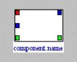
The exergy resources being of three possible types, and the products of two, a productive unit is represented by a rectangle with three inlet ports and two outlet ones, whose colors are differentiated in order to distinguish the various types of exergy flows and to allow to graphically separate resources and products.
The inlet port colors are the following:
red for fuel
blue for mechanical power
green for fluid exergy variation
The outlet port colors are:
blue for mechanical power
green for fluid exergy variation.
In a productive structure, the PDU are represented by rectangles, whereas lines which connect them correspond to the exergy flows which are exchanged: "fuels" at the inlet and "products" at the outlet.
As an exergy flow can be distributed between several PDUs, it is necessary to introduce what we shall name pseudo-nodes to represent the exergy mixers and dividers. In the productive structure, the mixers (or junctions) are depicted as rhombs, and the dividers (branches) as circles.
The exergy of a fluid going through a component can increase or decrease. If it increases, we shall say that the component is an exergy provider, if it decreases that it is an exergy receiver.
Exergy provider components
An exergy provider is represented by a productive unit with an output junction, with two incoming links: the one going out of the green port of the productive unit (outlet exergy flow), and the one corresponding to the inlet exergy flow.
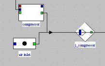
In this figure, the total exergy available at the outlet of pseudo-node "j_compressor" is the sum of two values:
first the exergy flow at the inlet of the component, represented by process-point "air inlet"
second the exergy variation of the fluid in the compressor, which gets it under a mechanical form.
The pseudo-mixer or junction "j_compressor" is used to model this addition.
Exergy receiver components
An exergy receiver is represented by a productive unit with a branch at the inlet, with two outgoing links: the one arriving at the green port of the PDU (inlet exergy flow), and the one corresponding to the outlet exergy flow.
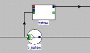
On this figure, the total exergy available upstream of the turbine separates in two parts:
first the one which is the turbine "fuel" and is converted under a mechanical form
second the one which remains available at the turbine outlet.
The pseudo-divider or branch "b_turbine" is used to model this division.
Exergy balance screens
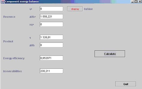
Double clicking the productive unit opens a screen which allows some settings in order to calculate component exergy resources and products, as well as irreversibilities and exergy efficiency, which, by shortcut, we denote by establishing the exergy balance of the component.
The Figure below shows the screen of a turbine PDU whose exergy balance can be determined without specific settings: the exergy resource is provided by the fluid exergy variation (DeltaXh+), the product is the mechanical power (tau+), and the exergy efficiency and irreversibilities are also determined.
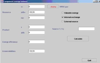
When the component is of the exchange type (Figure below), different possibilities exist.
If it is a fluid inlet or outlet, which corresponds to a process-point connected only upstream or downstream, its total (physical and chemical) exergy must be taken into account. Note that this may influence the overall balance because the methods of calculating various exergy properties are not the same;
If it is a fluid outlet rejected in the environment, the exergy is lost, which corresponds to an irreversibility. If on the contrary this exergy has an external value, it is an exergy product without irreversibility. The exergy calculation screen is provided with an option to specify this (Valuable exergy);
When internal heat exchanges occur, as for instance in combined cycles, the exergy loss calculation must also be modified: it is equal, in absolute terms, to the algebraic sum of the exergy variations of both fluids exchanging heat. The component exergy balance screen has an option (Internal exchange) for this setting. We shall see later that, in the overall exergy balance, the exergy variations of both fluids are displayed between brackets, the two exchange processes being grouped next to one another for clarity;
Lastly, when heat exchange takes place with an external energy source, the heat-exergy involved must be assessed, which requires the knowledge of the source temperature. This information may be entered in the exergy balance screen. The exergy calculation screen is provided with an option to specify this situation (External Source), and a field for entering the source temperature.
Note :
Examples of productive structures and exergy balances
Three of these exemples are presented in the getting started guide on the productive structure editor.
Steam power plant
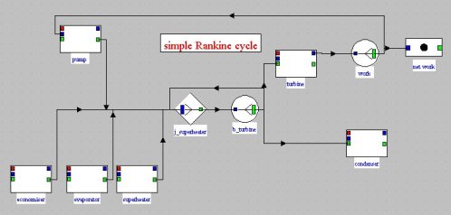
Productive structure
This productive structure is interpreted as follows: the steam power plant is a machine which receives an external exergy input in the boiler, and by internal recycling, exergy is provided to the pump, which are the two production units in the left of the screen. This exergy is partly converted into mechanical form in the turbine and partly dissipated in the condenser. The net work is the fraction of mechanical power not recycled.
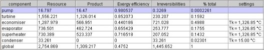
Exergy balance
Cogeneration gas turbine
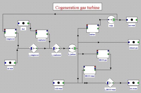
Productive structure
This production structure is interpreted as follows: the gas turbine receives a chemical exergy supply from the fuel, and by internal recycling, exergy is provided to the compressor. This exergy is converted partly into mechanical form in the turbine and partly into heat in the recovery steam generator HRSG, the remainder being dissipated by discharge into the atmosphere. The net work is the fraction of mechanical power not recycled.
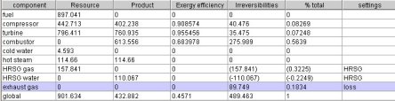
Exergy balance
Combined cycle
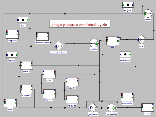
Productive structure
The combined cycle production structure is interpreted as follows: the gas turbine receives a chemical exergy supply from the fuel, and by internal recycling, exergy is provided to the compressor. This exergy is converted partly into mechanical form in the turbine and partly transmitted to the steam cycle by the exchangers the heat recovery steam generator HRSG, the remainder being dissipated by discharge into the atmosphere. The latter cycle also receives, by internal recycling, a supply of exergy for the liquid compression. The available exergy is partially converted into the steam turbine, the rest being dissipated in the condenser.
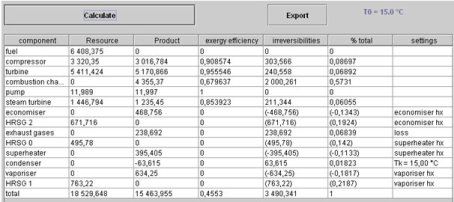
Exergy balance
Refrigeration cycle
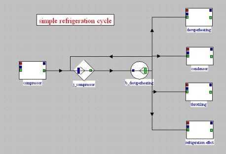
Productive structure
This production structure is interpreted very simply: the refrigerating machine receives an external exergy input in the compressor. This exergy is partly converted into the evaporator (refrigeration effect), the rest being dissipated in the condenser and the expansion valve (throtlling).
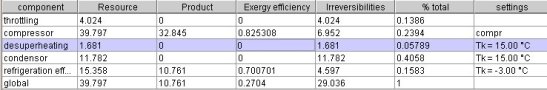
Exergy balance
Two stage total injection refrigeration cycle
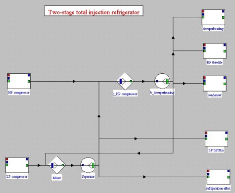
Productive structure
This production structure is interpreted very simply: the refrigerating machine receives an external exergy input in the two compressors. This exergy is partly converted into the evaporator (refrigeration effect), the rest being dissipated in the condenser and the expansion valves (throtlling).
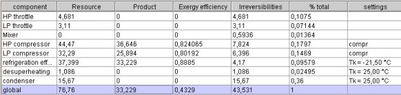
Exergy balance
Reference
Valero, A., Serra, L., Uche, J., Fundamentals of thermoeconomics, lectures 1-3, Euro summer course on sustainable assesment of clean air technologies, which can be downloaded from the CIRCE Web site.
Thermoptim reference manual, Volume 4.
The document below explains how the various types of components most generally used in energy systems (which are included in Thermoptim's core) can be represented as PDUs.
