GT exercises (setting out)
The exercises below are available to develop your modeling capability with Thermoptim. The statements being very brief, the diagram is provided in each case. Once the model is established, you can do sensitivity studies to analyze the influence of various parameters on the cycle performance.
The corrections are accessible to authentified teachers. The files provided are for Windows. As these are text files, it may be necessary to convert them for Macintosh or Linux.
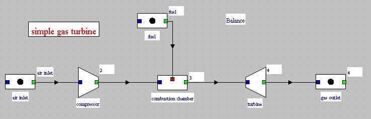
1) Simple gas turbine
A gas turbine burning natural gas (without dissociation) sucks air at 15 °C and 1 bar and compresses it at 16 bar in a compressor of polytropic efficiency 0.85, then the burnt gases are expanded in a turbine of polytropic efficiency 0.85. The inlet temperature in the turbine is 1150 °C.
2) closed cycle gas turbine
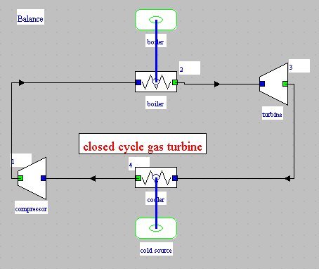
A closed cycle gas turbine sucks helium at 25 °C and 2 bar and compresses it at 18 bar in a compressor of polytropic efficiency 0.9. It is then heated at 950 °C in a boiler, and subsequently expanded in a turbine of polytropic efficiency 0.9. Helium is finally cooled at 25 °C by heat exchange with the cycle cold source.
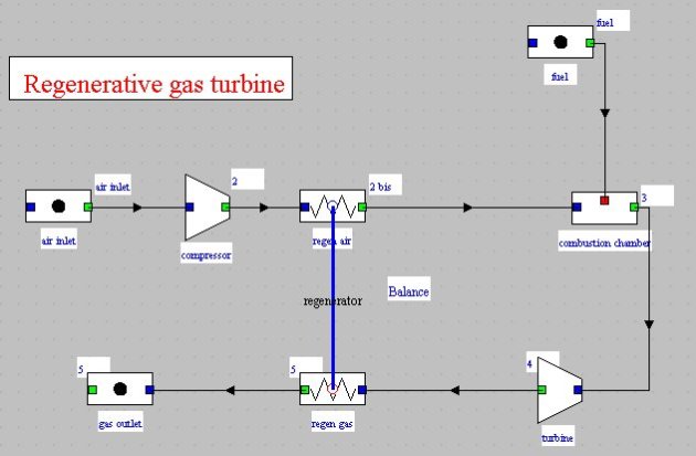
3) gas turbine with regeneration
This is a modification of the simple gas turbine, in which has been added a counter-flow regenerator of effectiveness 0.85. The suction gas temperature is 0 °C instead of 15 °C. The design of the heat exchanger is done without difficulty, a few iterations being however needed to calculate it given the coupling introduced in the system.
4) gas turbine with intercooler
This is a modification of the simple gas turbine, in which the compression work has been reduced by conducting a staged compression with intermediate cooling. The intermediate pressure is equal to 4 bar and the compressed air is cooled at 20 °C before entering the HP compressor. The intercooler is not modeled.

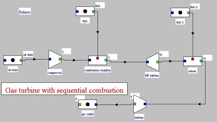
5) sequential combustion gas turbine
The gas turbine modeled here is similar to the Alstom Power GT24/26 machine. After a first expansion at an intermediate pressure, the gases are redirected into a second combustion chamber before being expanded in a LP turbine.
The inlet temperature in the LP turbine is 1255 °C, and the high and intermediate pressures are respectively 30 and 15 bar. The intake air flow rate is 549 kg/s.
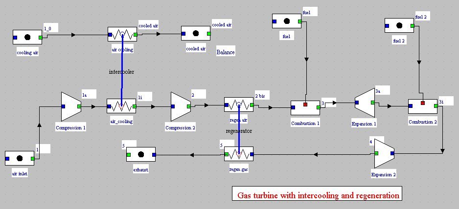
6) two-stage gas turbine
This is a two-stage gas turbine with intercooling, reheat and regeneration. This example, far more complicated than previous ones, involves two heat exchangers (cross-flow type, not mixed). One of them creates an inner loop: the regenerator. It illustrates the power of the recalculation engine Thermoptim. If you change any of the parameters of the cycle, as the inlet air or the end of combustion temperature, the recalculation engine is capable of finding alone the new solution, and this although the problem is particularly complex. Indeed, the temperature at point 2a depends on the operation of the regenerator, which itself depends on the gas composition and temperature at point 4, which themselves depend on state at points 3i, 3a, and 2bis...
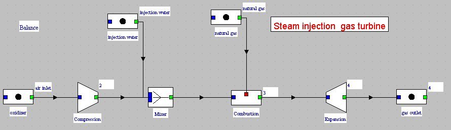
7) steam injection gas turbine
This is a modification of the simplegas turbine, in which is injected steam at 400 °C and 20 bar after air compression. The steam injection rate is equal to 10% of air flow and, for simplicity, the heat recovery steam generator is not modeled. The dissociation of CO2 is taken into account with a rate of 10% and a quenching temperature of 1 100 °C.
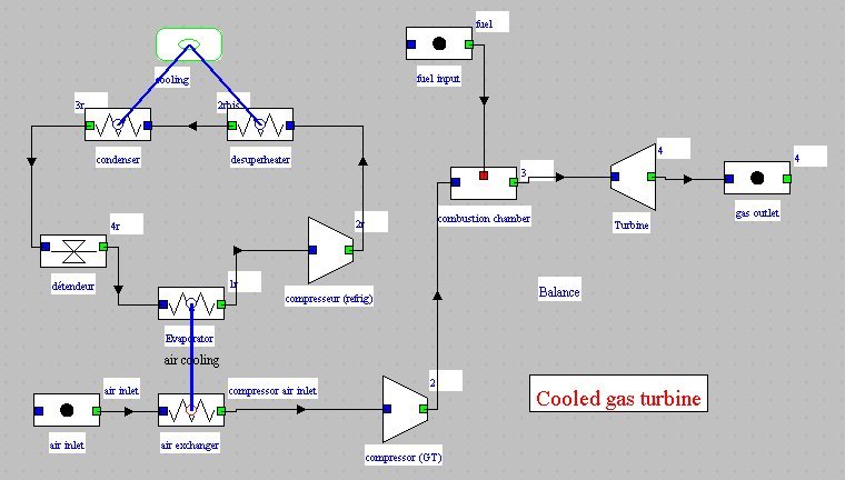
8) cooled gas turbine
This is still a modification of the simple gas turbine, in which intake air is cooled from 30 to 1 °C. The cooling cycle is a simple R134a cycle operating between 2 and 10 bar, with superheating and subcooling of 5 K, of the type presented section 6.2 of Part 2 (p2_6.2).
The modeling of each cycle is no problem. To ensure their coupling, adjust the flow of the refrigeration cycle so that the evaporator capacity matches that required to cool the inlet air. The solution is to select "set flow rate" in the evaporator, and to recalculate its flow through the exchanger by setting its inlet and outlet temperatures.