Electricity production
Introduction
Given its many benefits, electricity continues to experience a strong growth in the world, more than twice the rate of the growth of primary energy consumption since the oil shocks .
Electricity can be produced in many ways, from:
chemical energy (batteries, fuel cells);
coal or uranium (steam power plant);
gas or oil (steam power plants, gas turbines, combined cycle, diesel);
renewable energy (hydro, wind, photovoltaic, solar thermodynamic).
Batteries, solar cells and wind turbines can produce electrical energy locally, but they now represent a very small fraction of installed capacity, which is derived essentially from power plants.
Power plants convert into electricity either potential energy (hydropower) or heat (thermal and nuclear power plants). In almost all cases, the plant comprises a generator driven by a turbine.
Thermal power plants
Thermal power plants can be of several types.
Steam plants are the most common. They implement a thermodynamic fluid, most commonly water, and contain, besides the alternator, four components:
the boiler, hot source of the cycle, which, depending on the case, may be a combustion boiler (flame plant), or a nuclear boiler;
the turbine, comprising a large number of stages, grouped by high, medium and low pressure bodies, wherein the steam expands providing mechanical power;
the condenser, heat sink of the cycle, which condenses the working fluid being cooled, either by moist air in a cooling tower or by water from a river or the sea;
the pump, which, at the cost of negligible mechanical work, pressurizes water leaving the condenser.
Flame steam plants operate at high pressure and temperature (respectively of the order of 160 bar and 560 °C), much higher than those of nuclear power plants for security issues (respectively about 55 bars and 270 °C). Units reach a capacity of 600 MW for flame power plants and up to 900 MW and even 1450 MW for nuclear power plants. Their efficiencies are between 30 and 40%.
If you want to deepen the study of these reactor types, refer to the following thematic pages:
Gas turbines (GT) or combustion turbines (CT) facilities are most often used in open cycle, and sometimes in closed cycle. They consist of three basic components:
a compressor, usually centrifugal or axial, which is used to compress the ambient air at a pressure of between 10 and 30 bar in modern machines;
a combustion chamber in which fuel is injected under pressure, combusted with air previously compressed (the latter in large excess in order to limit the exhaust gases temperature at the turbine inlet);
a turbine, usually axial, in which the high temperature gases exiting the combustion chamber are expanded. A significant proportion (60-70%) of the work generated by the turbine is used to drive the compressor.
Two broad categories of gas turbines are generally distinguished: industrial gas turbines, heavy and robust, but of average performance (efficiency eta between 28% and 38%), and gas turbines derived from aviation or "aeroderivative" which are much more efficient and lighter (eta between 35% and 42%), but also more expensive. The capacities of the first range from tens of kW (microturbines) to several hundreds of MW, while those of aeroderivative machines are generally between a few hundred kW to tens of MW, corresponding to those of aircraft engines.
Most jet engines used in aviation today are in fact variations of the gas turbine open cycle. The aviation market has helped fund major technological development programs on these engines, which led to the development of highly efficient gas turbines, which could supplant industrial gas turbines, or allow turbine design consisting of enhanced efficiencies and low cost, including components of existing jet engines for high pressure compressor and turbine sections, and industrial parts for low-pressure sections.
Recent improvements have allowed GT efficiencies to go up to 33% for large power units (200 MW), and they are expected to reach nearly 40%.
One way to enhance the residual enthalpy of the exhaust gas is to use them as a heat source for a second cycle of production of mechanical energy. This new generation of power plants is called combined cycles (CC). The excellent efficiencies reached today by combined cycle power plants (above 60% LHV), are the result of integration into a single production unit of two complementary technologies in terms of temperature levels: gas turbines, which operate at high temperature (in an aero-derivative turbine gases typically enter at 1300 °C in the expansion turbine, and come out at around 500 °C), and steam plants, which operate at lower temperatures (between 450 °C and 30 °C in this case).
Diesel engines are also used for power generation.
Additional information
If you want further study of these machines, refer to the following thematic pages:
Production management
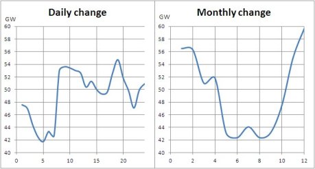
One of the major constraints in the production of electricity is undoubtedly the difficulty of storing the produced energy. Electricians must be able to adjust their production to meet the demand, which fluctuates strongly, either daily or on a seasonal basis. For example, Figure 2.5.1 shows the values of peak demand on the EDF network in France on January 19, 1989 and throughout the year 1989.
It is essential to ensure the continued adequacy of production to meet demand, otherwise complete network outages may occur. The most famous ones are those of August 2003 in the United States and Canada (which resulted in the shutdown of a hundred power plants in the Great Lakes the East coast), of November 2009 in Brazil (which affected a quarter of the country's population), and of July 2012 in India (a giant electricity blackout affected half of the country, after the almost simultaneous collapse of systems serving twenty states in the north, east and northeast).
Two basic strategies can be used to meet this requirement:
trying to reduce the load curve amplitude of variations by offering rates for users encouraging them to use off-peak electricity and divert peak power demand;
better managing the fleet of plants to minimize operating costs.
Firstly, the natural storage offered by lake plants is used by preferably operating these plants at peak times. Plants whose cost of fuel is lower are used during periods of base demand, reserving for the peak those whose investment cost is lower, even if the fuel cost associated with them is very high. Finally, energy that has a very low base cost (e.g. nuclear) is used to store water in lakes during low demand hours, and turbine it during peak hours (with a cycle efficiency of about 70%).
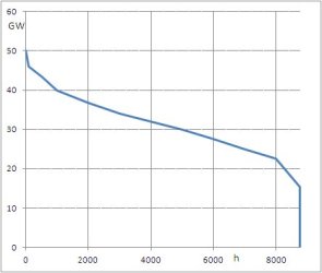
The power curve is presented as a series of electrical power required by the network . Its use being inconvenient, electricians are accustomed to transform it by summing demand hours corresponding to a given power.
This gives the monotonic load curve or “monotone” (Figurebelow), where the abscissa gives the number of hours h during which power demand was greater than the value shown on the ordinate (it is a cumulative frequency curve). On this curve are placed the equipment depending on cost and proportional fixed cost [Gomez-Exposito & al., 2008]. The aim is for the total cost, fixed cost plus the proportional one multiplied by the number of operating hours to be minimal.
Transport and distribution
As electricity cannot be easily stored, it must be distributed instantly. This is the role of the network, which is composed of four sub-networks based on the current voltage, connected together by switching stations. Joule losses can be up to 7% of the total production.
Placed at the outlet of the plant, lines at very high voltage (VHV) transport electricity set at very high voltage (400,000 and 225,000 volts) over long distances. All VHV lines form an interconnected network allowing for the discontinuation of certain plants.
Production and energy movements are managed by dispatching control centers. These centers, assisted by powerful computers, establish production schedules based on forecasts and real-time data corrected to deal with contingencies.
The VHV network is connected to the networks of neighboring countries, which has the effect of increasing supply security in the event of a catastrophic failure, and allows for international trade in electricity.
High voltage lines (90,000 and 63,000 V) are, with VHV lines, the transport network. They are used to route electricity to distribution utility centers and large users (railway, chemical industries, steel, metallurgy).
The medium voltage network (between 15,000 and 20,000 V) supplies customers with medium users from distribution centers. In addition, it serves low-voltage through MV / HV transformers.
Low voltage lines (380 or 220 V) form, together with the MV lines, the distribution network. LV network supplies millions of domestic users.
Each of the four previous networks is connected to his or her neighbors by transforming stations, home breakers, designed to protect against network malfunctions, isolators, which allow, if necessary, to disconnect part of lines and transformers, which modify the voltage junctions between different networks.
