Introduction
We are going to study the model of a high temperature nuclear cycle.
Among the nuclear reactors envisaged in the future, a certain number would make it possible to produce electricity from architectures implementing gas turbines operating in closed cycle, and not open GT like those which we have studied so far.
This diagram corresponds to a helium Brayton cycle envisaged for small PBMR (Pebble Bed Modular Reactor) reactors, using as fuel low carbon enriched uranium pebbles (which plays the role of moderator) and using helium as a heat transfer fluid.
This cycle, which leads to excellent performance, has the drawback, however, that there are currently no suitable industrial turbomachines, and that it will take many years to develop them.
An alternative solution consists in using helium as coolant for the reactor core, and another gas as thermodynamic fluid, in particular a mixture of nitrogen and helium (79% N2, 21% He by volume), whose thermodynamic properties are relatively close to those of air for which industrial technology is well mastered.
This solution however requires the introduction of an intermediate exchanger called IHX for Intermediate Heat eXchanger (we then speak of an indirect Brayton cycle), the realization of which is not simple, even if it is more or less controlled, and which introduces irreversibilities which have the effect of lowering the overall efficiency.
Loading of the model
Let us study tBrayton helium cycle with intermediate exchanger.
Load the model
Click on the following link: Open a file in ThermoptimOpen a file in Thermoptim
You can also:
- either open the "Project files/Example catalog" (CtrlE) and select model m15.1 in Chapter 15 model list.
- or directly open the diagram file (PBMR_IHX_En.dia) using the
"File/Open" menu in the diagram editor menu, and the project file
(PBMR_IHX_En.prj) using the "Project files/Load a project" menu in
the simulator.
The setting of this model requires some explanation.
Model setting
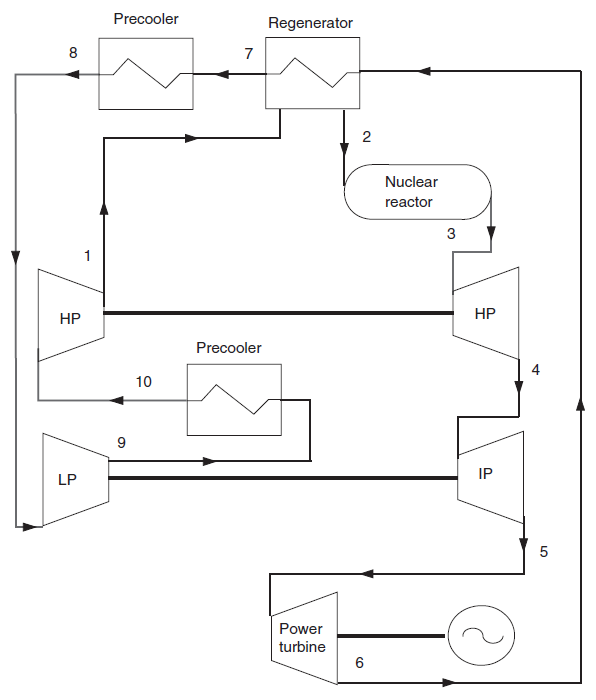
In this example, a flow rate of 700 kg/s of a mixture of helium and nitrogen compressed to 70 bar (1) enters a regenerator, which it leaves at approximately 565 °C (2) before cooling the intermediate exchanger (IHX) with the reactor core, from which it exits at 850 °C (3) and at 67.4 bar. This flow is expanded in two turbines (3–5) used to drive the two compression stages, before being expanded to 26 bar in a second turbine (5–6) which produces the useful power.
The cycle is closed by cooling the helium in two stages (regeneration (6–7) then cooling to around 28 °C (7–8) before being compressed.
In this example, the polytropic efficiencies of the turbomachines are assumed to be 0.9, as well as the effectiveness of the regenerator.
Each of the HP and LP turbines is mechanically balanced with the corresponding compressors.
The modeling of the pure helium circuit for cooling the reactor uses a compressor intended to overcome the significant pressure drops in the intermediate exchanger, which is a gas-gas exchanger whose heat exchange coefficients are low, which requires large exchange surfaces and small sections.
We assumed an average temperature difference of around 50 °C in this exchanger, but the price to pay is a consumption of more than 19 MW in the helium compressor.
Cycle plot in the (h, ln (P)) chart
First step: loading the helium and nitrogen mixture (h, ln (P)) chart
Click this button
You can also open the chart using the "Interactive Charts" line in the "Special" menu of the simulator screen, which opens an interface that links the simulator and the diagram. Double-click in the field at the top left of this interface to choose the type of diagram desired (here "Ideal gases")..
Once the diagram is open, choose "He-N2" from the substance menu, and select "(h, p)" from the "Chart" menu.
If you do not have access to the (h, P) gas chart, open the Help/Global Parameters menu in the Thermoptim simulator screen, check the option "(h, P) chart for gas" at the bottom left, then close the window by clicking on "OK".
Restart the Thermoptim browser and repeat this guided exploration.
The (h, P) charts should be displayable.
Modify the diagram settings via the "Chart/Parameters" menu, choosing a pressure range from 20 to 80 bar, and temperature from 20 to 920 °C.
Finally, modify the visible zone of the ordinate axis via the "Chart/Y axis" menu, choosing a pressure range from 20 to 80 bar.
Second step: loading a pre-recorded cycle corresponding to the loaded project
Click this button
- in the chart window, choose "Load a cycle" from the Cycle menu
- and select "PBMR_IHX.txt" from the list of available cycles.
- Then click on the "Connected points" line in the Cycle menu.
You get the cycle plot in the (h, ln (P)) chart.
Split compression appears on the left of the diagram, and expansion in several stages on the right.
The heat exchanges with pressure drops correspond to the plots close to the horizontal.
Application exercises
You can now perform sensitivity analyzes of the performance of this cycle to its various parameters, such as the intermediate compression pressure and the effectiveness of the regenerator.
Conclusion
This exploration allowed you to discover a Brayton cycle with intermediate exchanger model and the specific settings it uses.