Pressurized Water nuclear power plants (PWR)
Pressurized Water nuclear power plants
In nuclear power plants using steam cycles, heat can be provided either directly in the reactor (Boiling Water Reactor (BWR) not used in France) or by an intermediate heat transfer fluid which transfers heat from the nuclear reactor core (Pressurized Water Reactor (PWR) used in France).
In a Pressurized Water Reactor, for safety reasons, the maximum steam cycle temperature and pressure are limited at levels well below those used in flame plants. In current PWR plants (unit said N4), pressure in the generator is about 60 bar and the steam temperature rarely exceeds 275 °C.
The block diagram of a PWR is given in Figure below. On the left side of the diagram appears the containment structure comprising three main organs:
the reactor with its control system (control rod drive mechanism);
the steam generator;
the pressurizer.
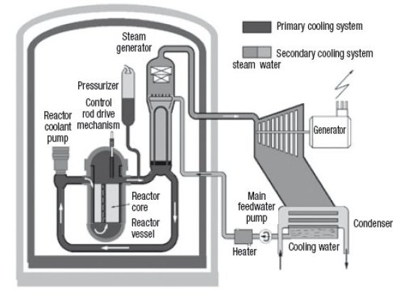
These three devices are connected by the primary circuit, including connecting pipes, and reactor coolant pumps, which circulate the coolant in the direction of the arrows.
The steam generator is connected to the secondary circuit located outside the containment structure, which corresponds to the thermodynamic cycle followed by steam, symbolized in the diagram by a turbine, condenser, feedwater pump and a heater.
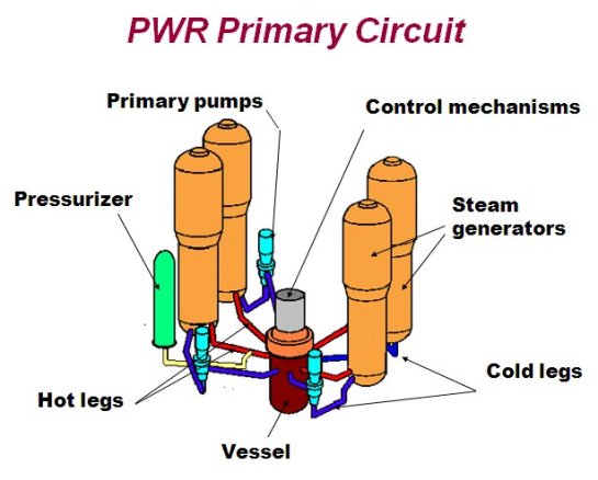
PRIMARY CIRCUIT
In a PWR, extraction of heat from the nuclear core involves two circuits for safety reasons, the cooling fluid (water under pressure) in contact with the reactor core being radioactive, due to fission products migrating through the cladding, and products dissolved in water (mainly due to corrosion), which capture neutrons. To prevent contaminated water from being in contact with the outside and passing through electricity production cycle components, the working fluid is separate from the coolant.
The choice of this fluid is based on the qualities of water as a coolant (high heat capacity), environmentally and for use (stability, safety, availability). However, it imposes a strong constraint: the need to ensure that water remains in liquid state in the reactor vessel, to avoid local superheating of the nuclear fuel due to the presence of steam inducing low heat exchange coefficients.
For this, water must be maintained at a pressure higher than the saturation pressure at its maximum temperature in the reactor core. The whole primary circuit needs to withstand this maximum pressure, which results in severe mechanical stresses. The whole of this circuit is sized accordingly, and the system pressure is regulated with great precision to avoid either an overpressure that could cause circuit leakage or rupture, or a pressure decrease, given the risk of boiling in the core and fusion of the fuel. The pressurizer role is precisely to ensure this function.
A compromise must be found between safety constraints, thermodynamic cycle efficiency and installation costs. In existing plants, the maximum temperature of the thermodynamic cycle is set at about 280 °C and the primary circuit at about 330 °C. Specifically, the temperature of the primary circuit changes from about 290 °C (zero power) to 325 °C (maximum power).
To ensure non-boiling primary water, the coolant system pressure is set at 155 bar, corresponding to a saturation temperature of 345 °C, which provides a small safety margin. Such pressure is already high and imposes severe technological constraints at all levels.
To accurately control the primary circuit pressure, the pressurizer is a reservoir containing water in two-phase state, pressure and temperature being linked by the saturated pressure law.
To control the pressure, one simply regulates the temperature, which is done by heating or cooling (by spray) water in the pressurizer.
It is in communication with the entire primary system, and sets its pressure (Figure above).
The rest of the primary circuit consists of three pump unit/steam generator sets. Pumps have just the role of ensuring that the primary water circulates throughout the reactor, and simply offset the pressure drops (about 8 bar).
STEAM GENERATOR
The steam generator (SG) is able to transfer the total power of the reactor to the secondary circuit, with a very low temperature difference, as the performance of the thermodynamic cycle increases as its temperature does.
We have seen that the primary water temperature varies between 290 and 325 °C. The presence of feedwater heaters in the secondary circuit (see below), makes the secondary water enter the generator at a temperature of about 220 °C.
The current performance of the SGs used in PWRs (Figure above) lead to a maximum output temperature of about 275 °C.
Given the low temperature differences between primary and secondary circuits, the need to transfer significant power forbids in practice achieving any superheating in the SG, because the exchange coefficients between the primary liquid and superheated steam would be too small.
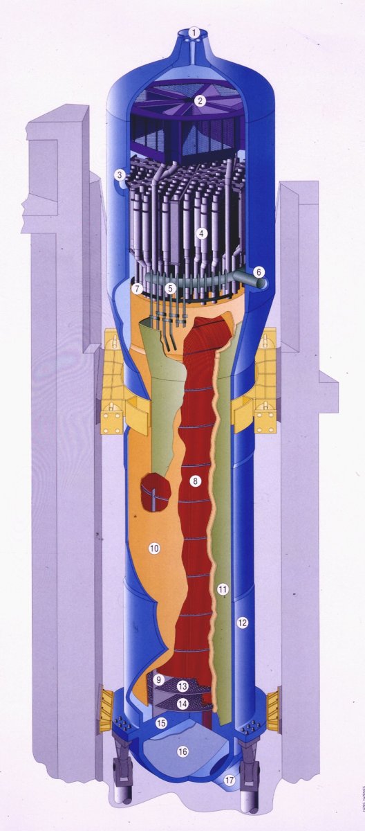
Therefore, the type of steam generators used by virtually all manufacturers of nuclear boilers corresponds to Figure 6.3.3.
Primary water enters the SG in the lower part of the unit via a pipe hidden in the figure, and symmetric of port 17, from which it exits cooled. This water passes, from the bottom up in the back of the figure, and down in its front, inside perforated plates designed to distribute the flow between the inverted U-shaped tubes (bundle 8).
Water from the secondary circuit enters in pipe 6 in the liquid state at a temperature of about 220 °C and a pressure of about 70 bar. It is distributed in the periphery of the SG by torus 5, provided with tubes that allow it to flow into jacket 11 located between the outer wall 12 and the bundle 10, which acts as economizer. It then follows an upward flow around the bundle, inside envelope 10, and partially vaporizes with a steam quality between 0.2 and 0.4, in a regime of nucleate boiling leading to very high heat exchange coefficients.
The two-phase emulsion then passes through cyclone separators 4 and then dryers 2. The liquid fraction falls to the bottom of the SG and is recirculated with the feedwater (the recirculation rate is between 2 and 4.5). The vapor fraction reaches a quality above 0.997, and exits through top port 1, to be directed towards the turbine high-pressure section.
SECONDARY CIRCUIT
A peculiarity of PWR nuclear power plant SGs is, as we have seen, that there is no initial superheat. Complete expansion of steam from this state would lead to too low a steam quality, which would be both disadvantageous in terms of performance, and fatal to the mechanical strength of turbine blades. The solution adopted consists in using a special organ called the moisture separator reheater (MSR), to split the expansion by providing a reheat at a pressure of about 11 bar, which can increase efficiency and meet the quality constraint at the end of expansion.
A moisture separator reheater (Figure below) receives steam partially expanded with a quality close to 0.87, the liquid phase of which is separated and directed to feedwater heaters, while the steam passes through a heat exchanger traversed internally by a low flow of saturated steam at high pressure (and therefore higher temperature), which condenses. On the cutaway of figure 6.3.4, live steam enters in 1 and leaves condensed in 2, while the steam to be superheated enters in 3 and exits in 4, condensate discharges being done in 5. For a 1,500 MW unit, two moisture separator reheaters of 370 tons each are needed. 24.8 m long, their height is 6 m and their width 5.3 m.
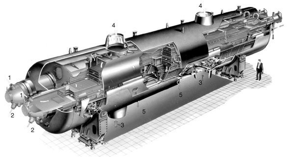
Figure below shows a synoptic view of a N4 PWR (excluding extractions) modeled in Thermoptim guidance page FG15 . The model of the moisture separator reheater is given in the upper right of the figure. It includes a separator (named dryer on the diagram) and a heat exchanger between average pressure steam and the extraction of saturated steam at high pressure (called superheater in the diagram).
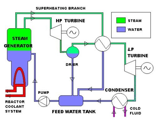
At the steam generator outlet, a fraction of the flow is diverted to the superheater, while the main stream is expanded at 11 bar. A separator recovers the vapor which is superheated by exchange with the fraction of flow which was discussed above. Superheated steam is then condensed and expanded, and headed towards the feedwater tank where the other streams flow. Water is then delivered under pressure to feed the steam generator. The synoptic view of this N4 PWR cycle is given below.
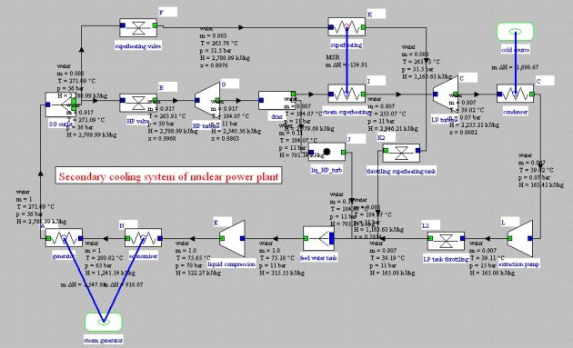
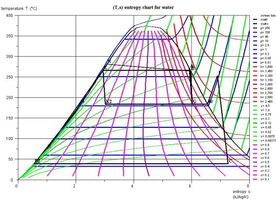
The cycle efficiency is equal to 31.4%. The extractions that actually take place allow it to reach about 33.5%. The cycle plot on a water entropy chart is given below.
Among other nuclear plant cycle features, we must mention the large value of flow rates. In fact, on the one hand the useful work per unit of flow rate is about 60% lower than in conventional coal or oil plants, on the other hand their optimum technical and economic unit capacities are much larger (900 or 1300 MWe against approximately 600 in the others).
Mass and volumes flow rates are very high. At turbine low-pressure section exit, velocities must be limited to increase efficiency and protect the condenser, which leads to design giant turbines (diameter up to 7 m) with very large sections of passage. The only solution to meet the mechanical constraints at the end of the blades is therefore for these important capacities, to halve the rotation speed of the turbine, which is then 1500 rpm.
